Do you have a question about the Honeywell SILENT KNIGHT SK-PS6 and is the answer not in the manual?
| Output Voltage | 24 VDC |
|---|---|
| Output Current | 6.0 A |
| Operating Temperature | 32°F to 120°F (0°C to 49°C) |
| Input Voltage | 120 VAC, 60 Hz |
| Battery Charging Capacity | 7.0 A |
| Humidity Range | 93% RH, non-condensing |
Tests required after system changes, programming, or component modifications.
Equipment compliance with FCC rules for radio frequency energy emissions.
Apparatus compliance with Canadian radio interference regulations.
Process for providing comments and suggestions to improve documentation.
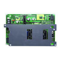
General description of SK-PS power supplies and their applications.
Details the key features and capabilities of the SK-PS power supply.
Provides technical specifications including power, current, and voltage ratings.
Defines resistance values for detecting open, short, and ground faults.
Description of SW1 switch functionality for enabling/disabling ground fault detection.
Details various applications and use cases for the SK-PS power supply.
Step-by-step guide for powering up and initiating the SK-PS power supply.
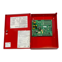
Instructions for mounting the SK-PS backbox securely to a wall.
Guidance on wiring Notification Appliance Circuits (NACs) in Class B and Class A configurations.
Details the standard Class B configuration for NAC circuits.
Describes the ZNAC-PS module for converting outputs to Class A NACs.
Instructions for mounting compatible addressable modules onto the SK-PS circuit board.
Details NEC requirements for separating and wiring Class 2 power-limited circuits.
Configuring the SK-PS as a slave unit connected to a master FACP for synchronized output.
Connecting the SK-PS as a master unit to an FACP for synchronization.
Explains the daisy-chaining method for connecting multiple SK-PS units.
Methods for monitoring ground faults when cascading or daisy-chaining power supplies.
Procedure for connecting the SK-PS to a CHG-120F external battery charger.
Procedure for connecting the SK-PS to a CHG-75 external battery charger.
Details how to cascade up to four SK-PS units for additional NAC extenders.
Details the function of S1 DIP switches for global options and UL-compliant settings.
Configures signal stabilization time to prevent false triggers from input signals.
Defines how Command Input #1 controls output circuit activation based on sync or trigger signals.
Option to disable the onboard charger, typically for external charger use.
Sets the delay for door holder power loss after AC power failure.
Allows delaying the trouble signal generation upon loss of AC power.
Describes Default Mode, Retrofit Mode, and temporary configuration/history modes.
Details how DIP switches S2-S8 control individual output circuit functions.
Configures NAC circuits to activate based on selected command inputs.
Instructions for setting unused output circuits to the OFF position.
Configures output circuits as resettable or non-resettable auxiliary power sources.
Configures output circuits as door holder circuits with specific activation logic.
Configures outputs for Master or Slave synchronization of notification appliances.
Enables silencing of sounders while keeping strobes active in Master Configuration.
Enables Class A wiring for NAC and aux power circuits using the ZNAC-PS card.
Specifies the maximum number of strobes that can be connected per circuit.
Indicates the status of ground fault detection on the power supply.
Indicates the power status, including AC power loss or brownouts.
Indicates battery charging or fault conditions.
Red LEDs indicating the active or inactive state of output circuits.
Yellow LEDs indicating wire supervision or power limit faults for output circuits.
How input circuits are used to report various power supply troubles to the FACP.
Details the Form-C trouble relay at TB1 for monitoring system faults.
Describes the AC trouble relay at TB2 for reporting AC power loss conditions.
Overview of calculating power supply currents and battery requirements.
Guides on calculating the required AC branch circuit current for the system.
Steps to calculate system current draw for non-fire alarm and fire alarm conditions.
Detailed instructions and tables for calculating system current draws.
Guidance on selecting and locating batteries based on power requirements.
Details NFPA 72 requirements for standby and alarm power for fire alarm systems.
Provides tables for maximum battery standby loads for 24-hour standby on SK-PS6 and SK-PS10.
Essential procedures for periodic testing and servicing of the power supply.
Maintenance guidelines for sealed lead-acid batteries, including replacement.
Lists NAC wiring requirements based on load, resistance, and wire gauge.
Example of using a control module for selective silence operation with synchronized NACs.
Example of using a control module in Slave Configuration to follow FACP sync signals.
Demonstrates controlling NACs, aux power, or door holders with one input via a control module.
Example of monitoring trouble relays and triggering outputs using a SK-RELAYMON-2 module.
Example of controlling all three command inputs using a single SK-CONTROL-6 module.
Configuring AC trouble reporting with a conventional FACP lacking a type-coded input zone.