Do you have a question about the Honeywell SILENT KNIGHT SK-PS10 and is the answer not in the manual?
Details the technical specifications, including voltage and current ratings.
Defines resistance values for detecting circuit faults in standby mode.
Explains the function and operation of the SW1 ground fault detection switch.
Outlines various use cases and applications for the SK-PS power supply.
Provides a step-by-step guide for the initial setup and powering of the unit.
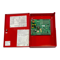
Instructions and diagrams for mounting the power supply backbox.
Details on how to wire Notification Appliance Circuits (NACs).
Explains wiring requirements based on NEC Class 2 power-limiting standards.
Illustrates connecting the SK-PS as a slave unit to a master FACP.
Shows how to configure the SK-PS as a master for synchronization with an FACP.
Guidance on expanding system capacity by connecting multiple SK-PS units.
Overview of global configuration settings using the S1 DIP switch.
Detailed explanation of programmable features controlled by global DIP switches.
Configuration settings for individual output circuits using DIP switches S2-S8.
Detailed explanation of programmable features for each output circuit.
How input circuits are used to supervise power supply trouble conditions.
Criteria and steps for choosing and placing backup batteries.
Procedures for regular testing and servicing to ensure operational reliability.
| Output Voltage | 24 VDC |
|---|---|
| Output Current | 10 A |
| Battery Charger | Yes |
| Operating Temperature | 32°F to 120°F (0°C to 49°C) |
| Humidity | 0% to 93% non-condensing |
| Input Voltage | 120 VAC |