SK-PS Series Instruction Manual — P/N LS10227-002SK-E:C 2/2/2022 15
Addressable Module Mounting Installation
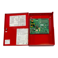
2.3 Addressable Module Mounting
The SK-PS has been designed to allow the mounting of an addressable control, relay, or monitor module on the main circuit board inside the
power supply cabinet. This allows power to be fed from an SK-PS output circuit directly to the module, if needed, without running the power
wires outside the cabinet. Remove mounting screws from the positions indicated below and replace with standoffs (included in hardware
kit). Mount the module over the standoffs and secure with screws.
Compatible modules include the SK-CONTROL, SK-MONITOR, SK-MONITOR-2, SK-RELAY, SK-RELAYMON-2, SK-CONTROL-6,
SK-RELAY-6, and SK-MON-10.
NOTE: PS-MOUNT, the optional hardware kit, ordered separately, contains all necessary hardware for mounting the ZNAC-PS onto the PCB
with an additional multi-point module.
*If the SLC device does
not match the one in this
figure, refer to the SLC
manual wiring conver-
sion charts for legacy
and newer versions of
the modules.
Figure 2.4 Mounting a Single Module in the SK-PS Cabinet
Install stacked standoffs
(0.5” + 1.093” M/F)
–
+
–
+
–
+
T
1
0
J
1
B
A
S
E
A
D
D
R
E
S
S
+
0
B
A
S
E
A
D
D
R
E
S
S
+
1
B
A
S
E
A
D
D
R
E
S
S
+
2
B
A
S
E
A
D
D
R
E
S
S
+
3
B
A
0
1
2
3
4
5
6
7
8
9
1
0
1
1
1
3
1
4
1
5
1
2
0
1
2
3
4
5
6
7
8
9
AC AC1 2
TB4
TB15
T
B
3
T
B
2
T
B
1
O
U
T
6
O
U
T
5
O
U
T
4
O
U
T
3
O
U
T
2
O
U
T
1
O
U
T
6
O
U
T
5
O
U
T
4
O
U
T
3
O
U
T
2
O
U
T
1
A- B+ B- A+ A- B+ B- A+ A- B+ B- A+
install 1.093” M/F
standoffs
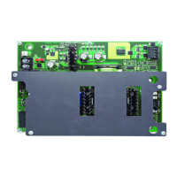
Note: For instructions on mounting a multi-module and a ZNAC-PS module, refer
to the ZNAC-PS Install Sheet #LS10228-000GE-E.
The multi-module must be installed upside down when the ZNAC-PS is installed. If
the ZNAC-PS is not installed, the multi-module may be mounted in either direction.
Figure 2.5 Mounting a Multi-Module in the SK-PS Cabinet
 Loading...