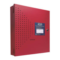
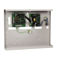
Do you have a question about the Honeywell Notifier ACPS-610/E and is the answer not in the manual?
Lists key features of the ACPS-610/E, including addressability, synchronization, output capabilities, and interfaces.
Details the function and meaning of each LED indicator on the ACPS-610 for status and troubleshooting.
Outlines the separation requirements for power-limited and non-power-limited wiring within enclosures.
Provides step-by-step instructions and safety warnings for connecting the ACPS-610 to the primary AC power source.
Details the procedures for installing and connecting batteries to the ACPS-610 power supply.
Explains how to select the appropriate battery charger current setting using PK-PPS software based on battery capacity.
Details the procedure for connecting two batteries to the ACPS-610 power supply, including charger setting.
Outlines the steps for connecting four batteries to the ACPS-610 power supply, including interconnect cable usage.
Details connecting Notification Appliance Circuits (NACs) and power outputs, specifying current limits and configurations.
Details how to set the SLC base address using rotary and slider switches (SW2, SW3) for address block determination.
Describes how to configure each of the four output circuits (NAC, power, door holder) using the PK-PPS software.
Details how to calculate standby and alarm DC current loads for the ACPS-610 outputs.
Guides on calculating maximum secondary power current requirements during standby conditions for battery sizing.
Guides on calculating maximum secondary power current requirements during alarm conditions for battery sizing.
Provides methods for calculating total secondary amp-hours needed for battery requirements.
Provides a table and method for determining the total secondary amp-hours required based on standby and alarm loads.
| Brand | Honeywell |
|---|---|
| Model | Notifier ACPS-610/E |
| Category | Power Supply |
| Language | English |
