ACPS-610/E Manual — P/N 53018:A1 07/31/2007 11
Board Layout Introduction
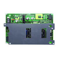
1.6 Board Layout
The ACPS-610 is comprised of two boards; the main control unit (the larger rear board), and the
KAPS-24/E power supply (the smaller front board). Figure 1.1 below illustrates the layouts for
these boards. Figure 1.2 illustrates the positions of the LEDs.
Figure 1.1 The ACPS-610 Board Layout
Ground Fault Switch
SLC Address
Rotary Switch
SW2
–
+
BATT
–
+
BATT
SLC Address
Slider Switch
Battery Fuse
F2
HOT
NEUT
SW3
EARTH
GROUND
SW1
USB Port
J3
SLC A
–
+
SLC B
–
+
UZC or
Synch input
OUTPUT 3
–
+
–
+
Out 3 COM
Out 3 +24V
Class A
Return
–
+
–
+
OUTPUT 4
Class A Return
Out 3 +24V
Out 3 COM
OUTPUT 2
–
+
–
+
Out 2 COM
Out 2 +24V
Class A
Return
Out 2 +24V
Out 2 COM
OUTPUT 1
–
+
–
+
Out 1 COM
Out 1 +24V
Class A
Return
Out 1 +24V
Out 1 COM
COM
+24V
+24V
COM
ACPS-610_board.cdr
(Replacement P/N 12057)

 Loading...