16 HPF-PS Series Instruction Manual — P/N LS10227-003HP-E:C 2/2/2022
Installation NEC Power-limited (Class 2) Wiring Requirements
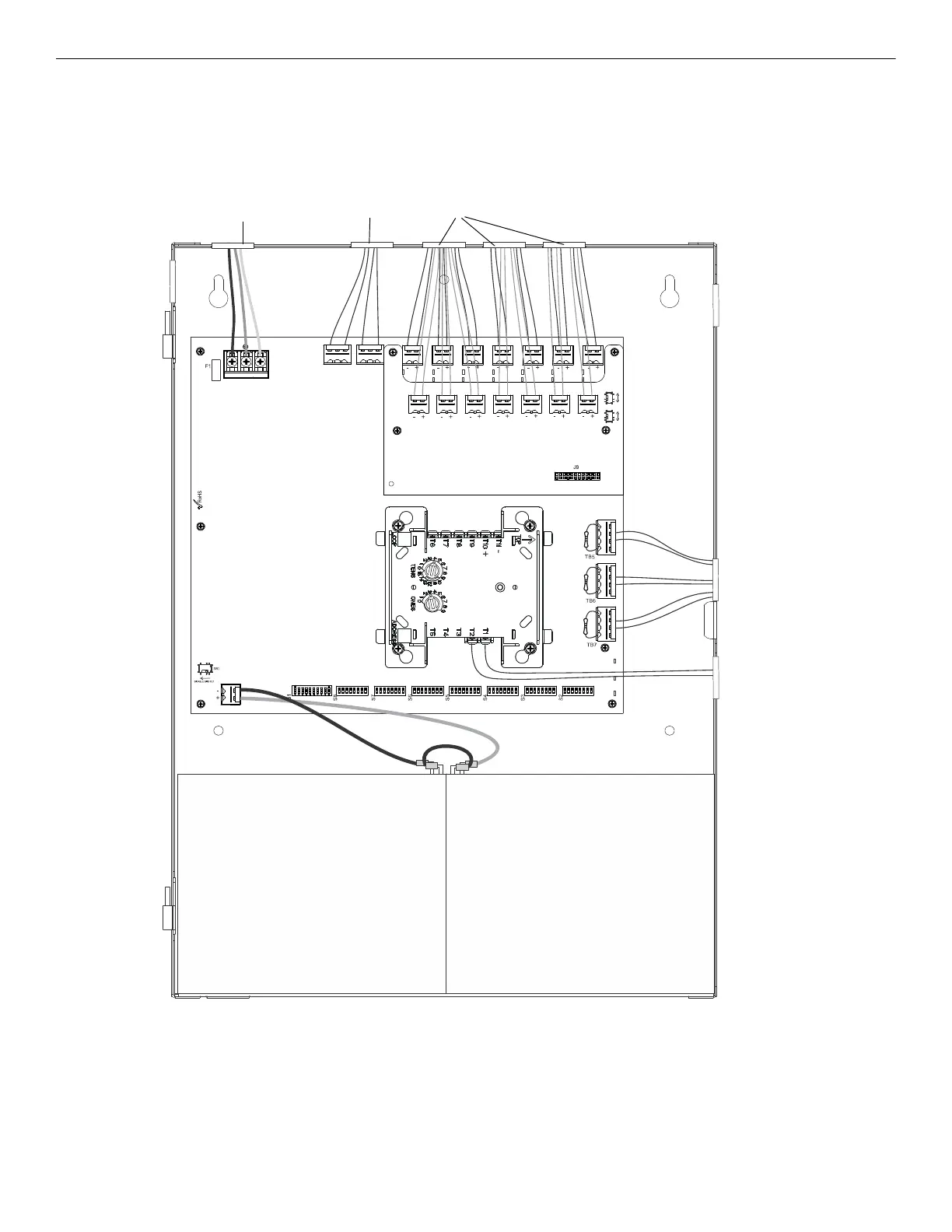
2.4 NEC Power-limited (Class 2) Wiring Requirements
Power-limited (Class 2) and non-power-limited circuit wiring must remain separated in the cabinet. All power-limited (Class 2) circuit wir-
ing must remain at least 0.25” away from any non-power-limited circuit wiring and all power-limited (Class 2) circuit wiring and non-power-
limited circuit wiring must enter and exit the cabinet through different conduits. One such example of this is shown below. Any conduit
knockouts may be used. For power-limited (Class 2) applications, use of conduit is optional.
NO NC CNONC C
TB4
TB15
T
B
2
T
B
1
T
B
1
3
T
B
1
2
T
B
1
1
T
B
1
0
T
B
9
T
B
8
2
A- B+ B- A+ A- B+ B- A+ A- B+ B- A+
Figure 2.6 Power-limited (Class 2) Wiring Example
AC Power
Non-power-limited
Output Circuits
Power-limited Circuits (Class 2)
Relay Contacts
Non-power-limited Circuit
Input Circuits
Power-limited Circuit
(Class 2)
SLC
Power-limited Circuits
(Class 2)
*If the SLC device
does not match the
one in this figure,
refer to the SLC man-
ual wiring conver-
sion charts for legacy
and newer versions of
the modules.
maintain minimum
0.25” between power-
limited and non-power-
limited wiring
 Loading...


