HM750A1000
13 33-00289—01
Low-voltage Controls
Requirements
• 18 AWG solid wire or greater.
• Low voltage wiring must be routed through the hole
that is to the left of the high voltage strain relief.
• Keep control wires as short as possible.
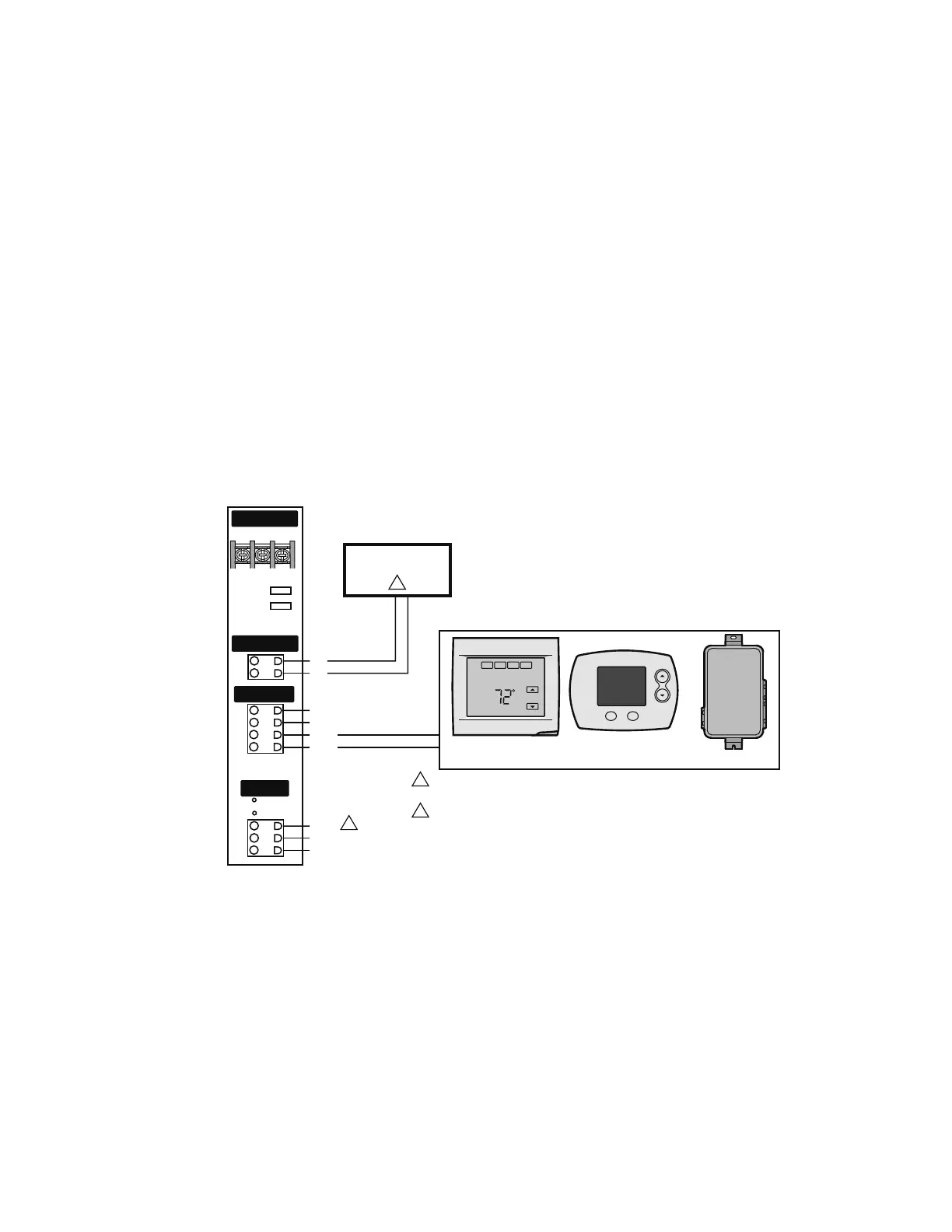
Wiring Procedure
The humidifier can be connected to the following three
devices (Fig. 23):
1. Humidistat or thermostat
2. Air Proving device (recommended)
3. External fan (optional)
Humidistat or Thermostat Connection
Connect a humidistat or thermostat to the
HUM
terminals
of the humidifier. The humidifier provides a 24-VAC source
to power the humidistat or thermostat if needed (5 VA max.).
NOTE: It is acceptable, but not recommended to install
the HumidiPRO in the furnace area (on duct). If
possible, locate the HumidiPRO in a high traffic
area inside the home.
Air Proving Device
Honeywell recommends the use of an Air Proving device
such as Honeywell Differential Pressure Switch
(50027910-001) to ensure steam is distributed only when
there is air circulation. Connect the air proving device to
the AP terminals. If you do not install an air proving device,
place a jumper between the AP terminals.
Fan Interlock
Connect an external fan (optional) to the EXTERNAL
terminals. The fan will turn on whenever there is a call for
humidity.
Fig. 23. Wiring the steam humidifier with a digital thermostat.
Fan Interlock Wiring with HumidiPRO
When distributing steam into a duct, there could be a call
for humidity when there is no air flow. The HM750 with
HumidiPRO control or some other thermostat can be
used to enable a fan on a call for humidity. If using another
thermostat, consult that control’s manual for wiring
instructions to enable the fan with a powered
humidification device.
NOTE: Humidifier will not start producing steam until
fan security loop is closed.
This information is relevant to all controls, factory
supplied or otherwise. For wiring use minimum 18 AWG
solid wire and keep as short as possible.
Humidity Control
• Can be located either in return air duct (preferred) or in
room being humidified.
• Avoid placing near discharge diffuser of humidified air.
• Mount in area representative of room humidity (drafts,
doorways, sunlight, or an overhang such as a shelf can
affect reading).
Optional Outdoor Temperature Sensor (included with
HumidiPRO)
• Mount outside in area representing air temperature.
AIR PROVING
(OR JUMPER)
THERMOSTAT, HUMIDISTAT, OR EQUIPMENT INTERFACE MODULE (EIM)
24VAC
COM
HUM
HUM
AIR PROVING JUMPER COMES PRE-INSTALLED.
REMOVE JUMPER IF AIR PROVING IS UTILIZED.
M36863B
AP
AP
GT
RF
GF
Main Supply
Air Proving
Humidistat
External
L1
L2/N GND
2
1
1
WIRING FOR FAN INTERLOCK EQUIPMENT (OPTIONAL)
2
J14J13
Equipment Interface Module (EIM)
 Loading...