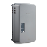
HM750A1000
9 33-00289—01
MOUNTING THE HUMIDIFIER
The HM750 can be mounted either directly on a supply air
duct or remotely mounted on a wall. When remotely
mounted the steam nozzle is mounted on a duct and
connected to the HM750 with a steam hose.
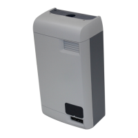
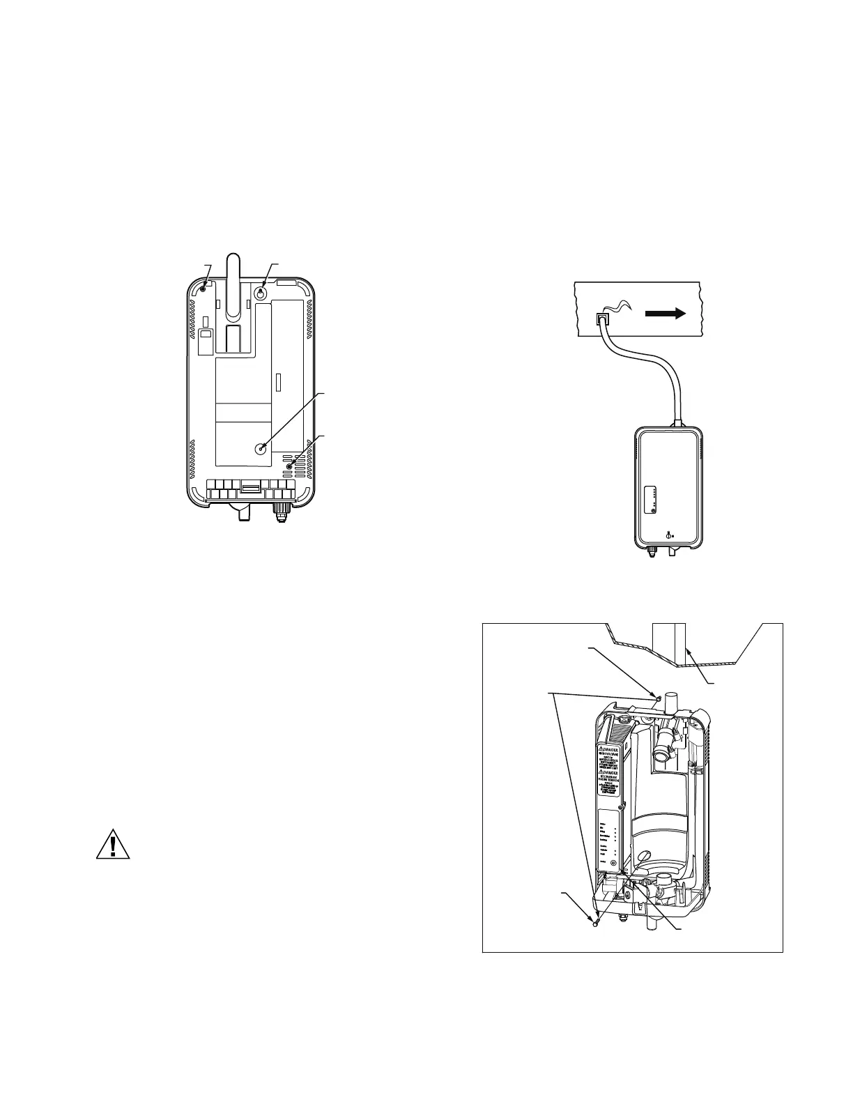
The HM750 has a keyhole and three additional mounting
holes as shown in Fig. 12.
Fig. 12. Mounting locations. (Rear view)
Mounting to a Wall
The HM750 comes in wall-mount configuration. In this
configuration, the humidifier can be mounted to a 2x4
stud and the steam distributor nozzle, located at the end
of a 5 ft. (1.5 m) steam hose, is inserted through the air
supply duct (Fig. 13).
NOTE: Use #8 screws at least 2 in. (5 cm) in length
(included) to mount directly to a 2x4 stud. Use
longer screws if the stud is behind a drywall or
other spacer.
NOTE: The steam distributor nozzle MUST be installed
higher than the humidifier (see Fig. 13). The
steam hose should maintain an inclination of at
least 4 inches (10 cm) of rise for every 12 inches
(30 cm) of run.
Do not remove the cover when the humidifier
powered.
1. Remove the humidifier cover and pull out the
cylinder. Insert the top screw until 1/4 in. (6 mm) is
exposed. Hang the humidifier via its keyhole on the
screw head (see Fig. 12).
2. After making sure the humidifier is level, affix it to
the stud with another screw at the lower stud-mount
location (Fig. 12).
3. Drill a 1-3/4” hole in the duct for the steam
distributor nozzle. Attach the steam hose to the
distributor nozzle and the remote adapter on the
humidifier. Then insert the steam distributor nozzle
and secure it with screws.
Fig. 13. Wall mount.
Fig. 14. Mounting with keyholes.
M36932
KEYHOLE
STUD
MOUNT
DUCT
MOUNT
DUCT
MOUNT
INSERT SCREW LEAVING
1/4 IN. (6 MM) EXPOSED.
HANG UNIT, THEN
TIGHTEN SCREW.
INSTALL SECOND
SCREW AFTER
HANGING
HUMIDIFIER
2X4 OR OTHER
STRUCTURAL
MEMBER
3 NUMBER 8 X 2 INCHES
(5 CM) WOOD SCREWS
NUMBER 8 x 2
INCHES (5 CM)
WOOD SCREW
M37235
 Loading...