HM750A1000
17 33-00289—01
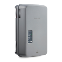
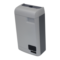
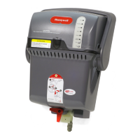
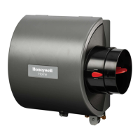
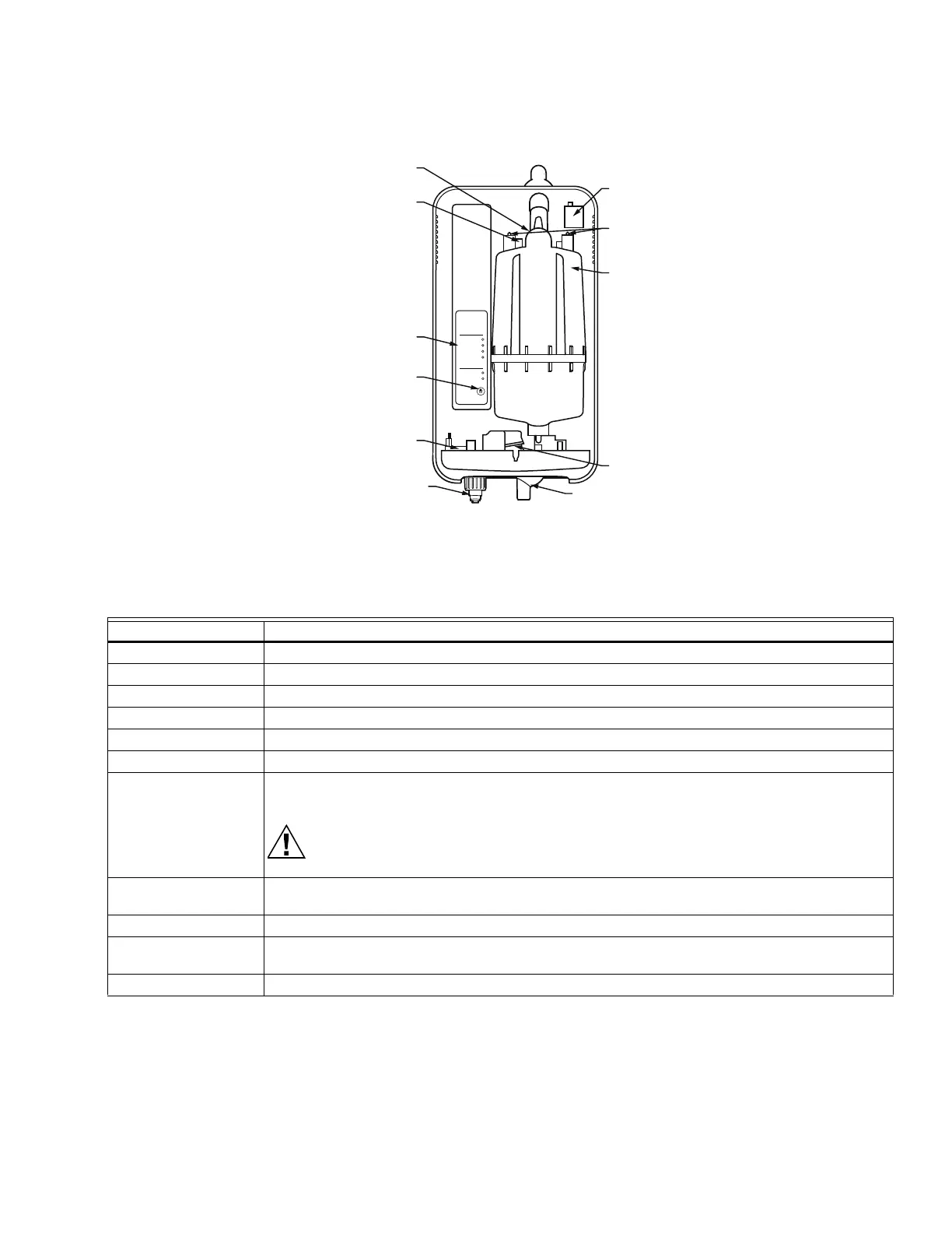
Fig. 26. Humidifier components.
HM750
Status
Service
Power
Idle
Filling
Humidifying
Draining
Cylinder
Fault
Drain
Fault Codes In Front Cover
M37211
STEAM
OUTLET
HIGH
WATER
SENSOR
USER
INTERFACE
POWER/DRAIN
BUTTON
FILL
VALVE
QUICK
CONNECTOR
DRAIN
OUTLET
DRAIN
VALVE
STEAM
CYLINDER
CYLINDER
PLUGS
FILL
CUP
Component Function
Cylinder plugs Power connectors to electrodes in cylinder.
Drain outlet Connection to drain hose, used to remove water from the humidifier.
Drain valve Drains water from humidifier.
Fill cup Provides an air gap for backflow prevention.
Fill valve Controls flow of water into humidifier.
High water sensor Used to detect maximum water level in cylinder.
Power/Drain button Used to turn the humidifier on or off. Note that before the humidifier turns off, the water in the
cylinder is drained.
The unit will still be powered internally even after being shut down.
Steam cylinder Steam generating vessel that holds electrodes in water. Current between electrodes generates
heat used to generate steam.
Steam outlet Connects to steam guide with short piece of steam hose.
Supply water
connection
Connection for supply water.
User interface Used to indicate the status of the humidifier to the user.
 Loading...