23
Mounting and Connection Instructions IB2 16 I/O Expander
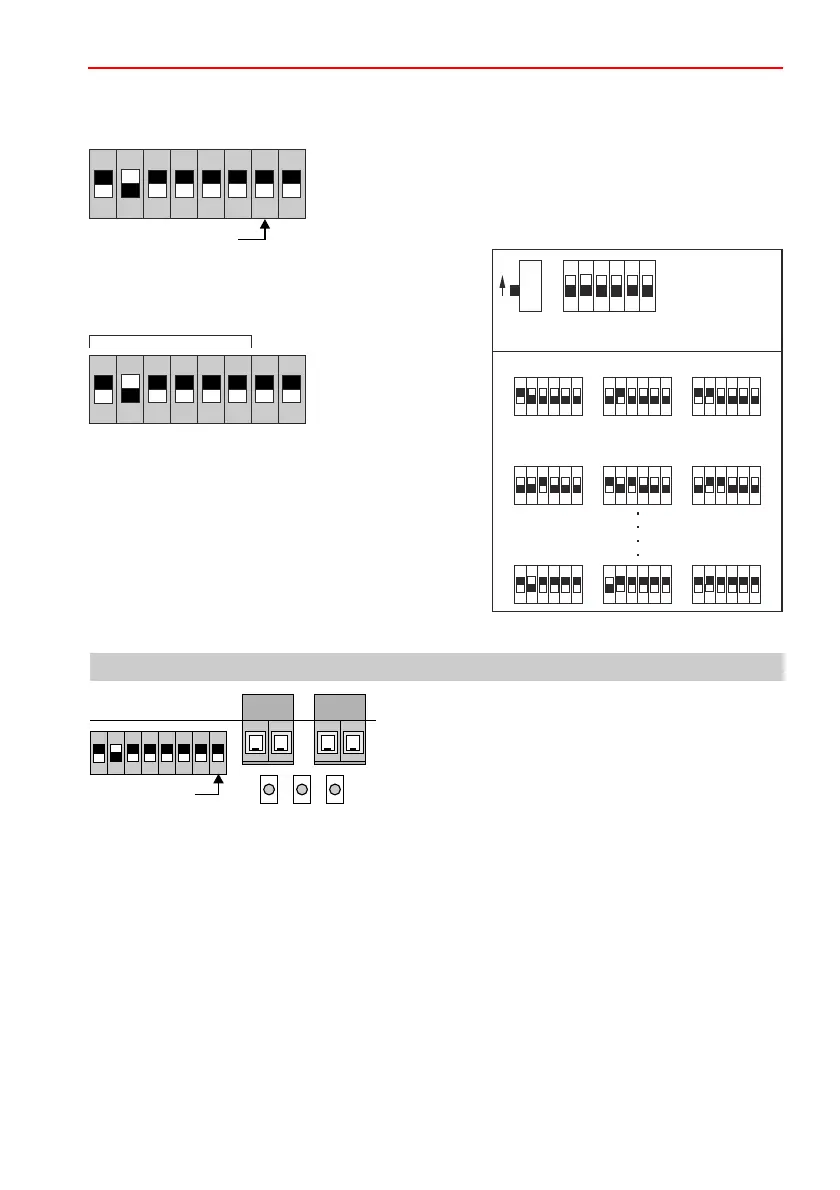
6.4 BUS-2 user address
BUS-2 address
7. LED indication
6.3 Bus operating mode
IB2 operating mode S7
BUS-2 operating mode S7
: in position ON
(no address required)
: in position OFF
LED indication
Bus operating mode
The DIP switch S8 is used to define the indication mode of the LEDs.
(The DIP switch S8 is accepted when in operation.)
(S8 in position )
LED flashes red Device has identified an error
LED lights up red UB is < 9.2 V, OK again when UB > 9.5V
LED flashes yellow Tamper
LED flashes green rapidly (0.5 sec.) Module is not polled
LED flashes green slowly (2 sec.) Module is polled
(S8 in position )
LED red lights up Status mode is activated
LED flashes yellow At least one input is not completed or at least one input is
activated as an output (clearing doesn't count).
LED flashes green At least one output is active.
LEDs in normal mode OFF
LEDs in status mode ON
32168
421
1 2 3 4 5 6
ONON
OFF
Valence
All switche s set
at "OFF" position
1 2 3 4 5 6
ON
1 2 3 4 5 6
ON
1 2 3 4 5 6
ON
1 2 3 4 5 6
ON
1 2 3 4 5 6
ON
1 2 3 4 5 6
ON
1 2 3 4 5 6
ON
1 2 3 4 5 6
ON
1 2 3 4 5 6
ON
Address 1
Address 4
Address 61
Address 2
Address 5
Address 62
Address 3
Address 6
Address 63
(Only when using as BUS-2 user)
Set the BUS-2 address using DIP switch S1 to S6.
The illustration shows the position and valence of
the switches.
In the event of several users, user must be
assigned its address.
1 to 63.
each
own
Permissible address range:
ON
1 2 3 4 5 76 8
ON
1 2 3 4 5 76 8
ON
1 2 3 4 5 76 8
LED 1 2 3
 Loading...


