24
Mounting and Connection Instructions IB2 16 I/O Expander
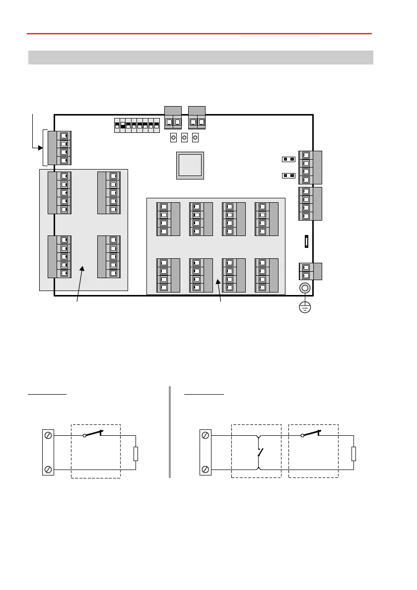
8. Connection diagram
8.2 Inputs
One of the following functions can be assigned to each input via the programming:
8.2.1 Detector group input with clear function
8.1 PCB overview
U_EXT: 5 - 30 V DC
Voltage for high-active
output
IB2- / BUS-2
from
control panel
IB2- / BUS-2
to next user
16 outputs 16 inputs
Shield
connection
Grounding bridge
Tamper connection:
Tear-off protection (Wall) Tamper switch (Tamper)
DIP switch
A/D
0V
UB
B
A/D
0V
UB
B
JP2
JP1
PE
0V
0V
3
4
0V
0V
7
8
0V
0V
11
12
0V
0V
15
16
0V
0V
13
14
0V
0V
9
10
0V
0V
5
6
0V
0V
1
2
13
14
15
16
0V
9
10
11
12
0V
5
6
7
8
0V
1
2
3
4
0V
0V
0V
U-EXT
U-EXT
1
2
3
4
CPU
ON
1 2 3 4 5 76 8
LED 1 2 3
Example 2:
Combination GBS – contact: , then contact.
End-of-line resistor 12k1 at end of line.
First GBS
NCC
12k1
or
10k
IN1 – 16
0 V
Example 1:
Contacts, e.g. opening contact,
bolt switching contact
NCC
12k1
GBS
IN1 – 16
0 V
 Loading...


