LTE-CF Installation and Setup Guide
6
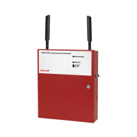
Mount the Communicator
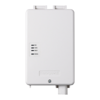
This communicator comes fully assembled with all the components mounted except the external
Antenna, and Antenna Mounting Adapter.
Refer to the Wiring Diagram on the inside of the back cover for wiring and component
identification.
For UL compliant installations, refer to the topic on Compliance in Section 1 of this manual.
For Dry/Indoor use only.
Unless otherwise specified, use 18AWG.
Installation must be in accordance with the National Fire Alarm and Signaling Code,
ANSI / NFPA 72.
1. Remove knockouts from cabinet to accommodate the wiring to the control panel, and internet
connection to a router. Then mount the cabinet securely to the wall using 4 screws or bolts.
Use mounting screws or bolts that are suitable for the material being anchored to.
2. Ensure the cabinet door lock is installed.
3. Connect and route 16AWG (minimum) insulated wire from facility power ground (typically a
cold-water pipe) to the cabinet's ground post. Ensure all ground connections are tight.
4. Ensure the following:
All wiring terminals and connectors are tight.
All wiring has been completed and secured with cable ties.
5. When the communicator wiring and programming (next section) is complete, lock the cabinet.

 Loading...

