
P
Patrick TurnerJul 26, 2025
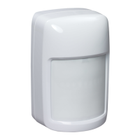
What to do if Honeywell IS335 Security System self-test fails?
- CChelsea LopezJul 26, 2025
If your Honeywell Security System's self-test fails, ensure the power supply provides at least 9V to the sensor. If the issue persists, try cycling the power to the sensor. Conduct a walk test of the sensor. As a last resort, replace the sensor if the trouble condition doesn't clear.