14 Installation Instructions MB-Secure 1000/2000/3000/4000/5000/6000
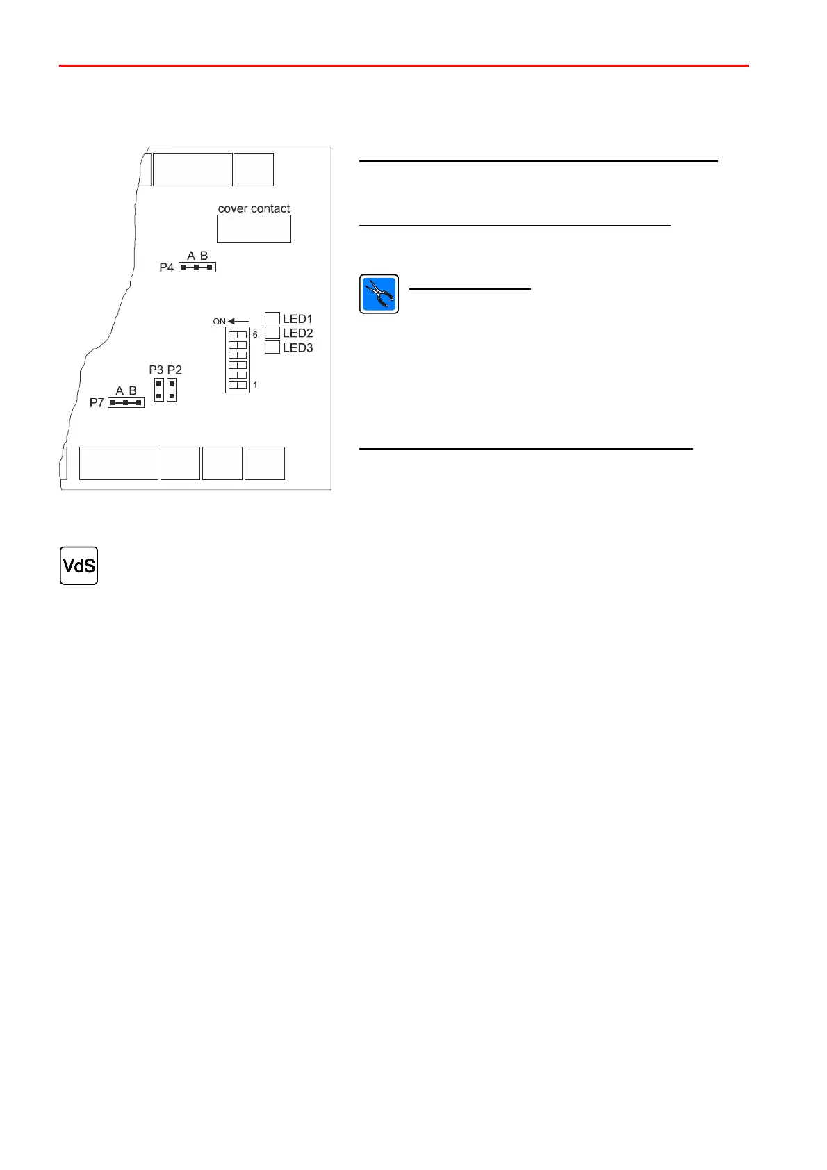
2.6.1.1 Programming jumpers/Monitoring resistors
Programming jumpers P2/P3 terminating resistors RS-485
P2/P3 connected: Terminating resistors active
P2/P3 not connected: Terminating resistors inactive
Programming connection P4 signalling device type
Position A: Signalling device 160455.10/160456.10*
Position B: Signalling device 048700/048720
Monitoring resistors
If signaling device 160455.10/160456.10* is
connected, the following monitoring resistors in the
signaling device must be changed
R1 10k -> 4k7
R2 4k7 -> 12k1
R3 0R -> 12k1
The corresponding resistors can be found in the
accessories pouch for the MB-Secure Siren module.
Programming connection P7 interface-operating mode
Position A: Interface-operating mode BUS-2
Position B: Interface-operating mode RS-485
(in preparation)
Signalling devices 160455.10/160456.10 must not be used in systems according to VdS.
 Loading...

