43-TV-33-65 iss.5 GLO Jan 21 UK 5
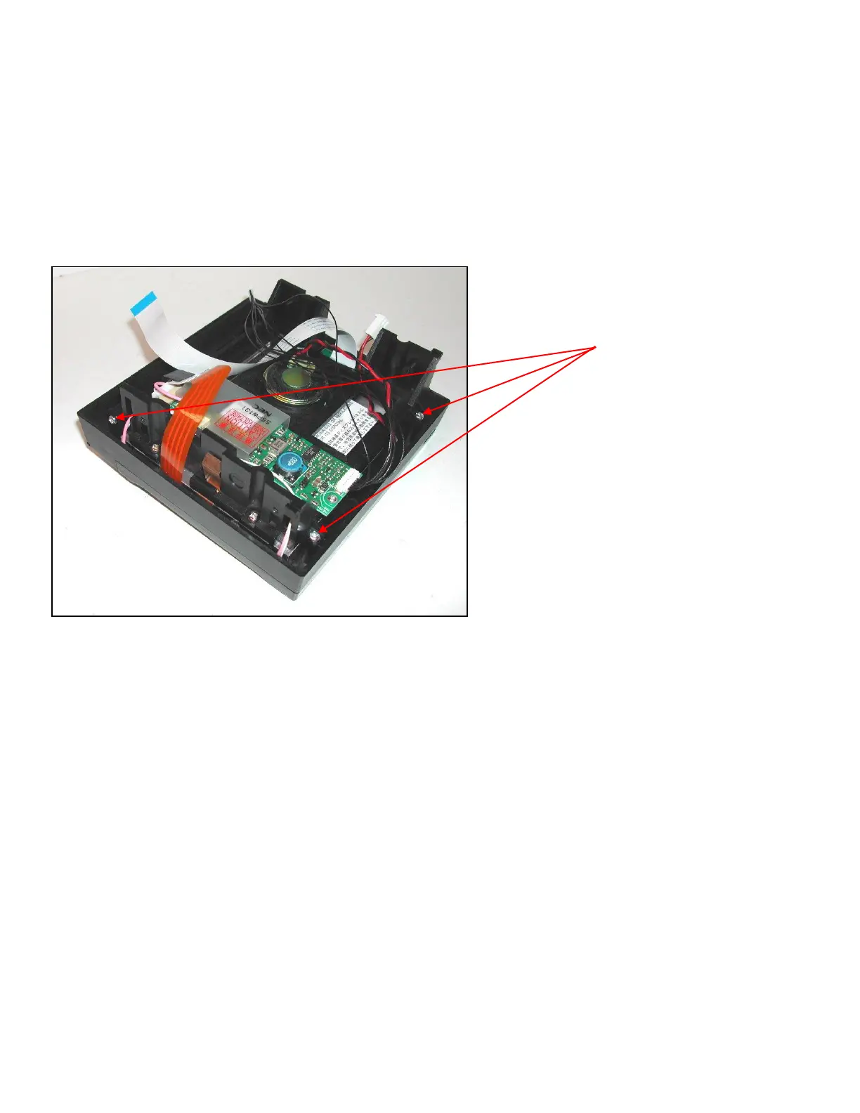
To remove the front bezel and touch screen assembly there are 4 self tapping screws that need to be removed, see Fig
7. Two screws are at the top of the assembly, and two screws are fitted one from each side. When these are removed
the display assembly can be separated.
Take care not to touch the display face or the back of the touch screen, any dirt or finger marks will show when the unit
is re-assembled.
The display assembly can now be lifted out of the Touch screen assembly. Remove the display assembly; ensure it is
placed on something that will prevent it getting scratched or dirty.
Carefully place the display assembly into the new touch screen/bezel assembly, ensure no cables are trapped.
Re-building the recorder
Rebuilding the recorder is the reverse process.
Carefully remove the protective covering from the back of the touch screen.
Before refitting the bezel/touch screen assembly clean any dirt or marks form the back of the touch screen or display.
Use a lint free cloth to clean both parts, do not use any solvents.
Take the display assembly and place it back into the bezel/touch screen assembly. Fit the 4 self tap screws that attach
the two parts.
Offer up the front surround to the unit.
Reconnect the cables. The inverter cable and the speaker cable are polarised and must be fitted the correct way round.
The touch screen connector must be fitted the same way round as it was removed. The cable must not have a twist in it.
It should be fitted so that the top wire as it comes out of the bezel is towards the centre of the board. The new touch
screen will not need an extender cable, so if one was fitted on you original screen this can be discarded.
 Loading...