43-TV-33-56 iss.4 GLO Aug 19 UK 11
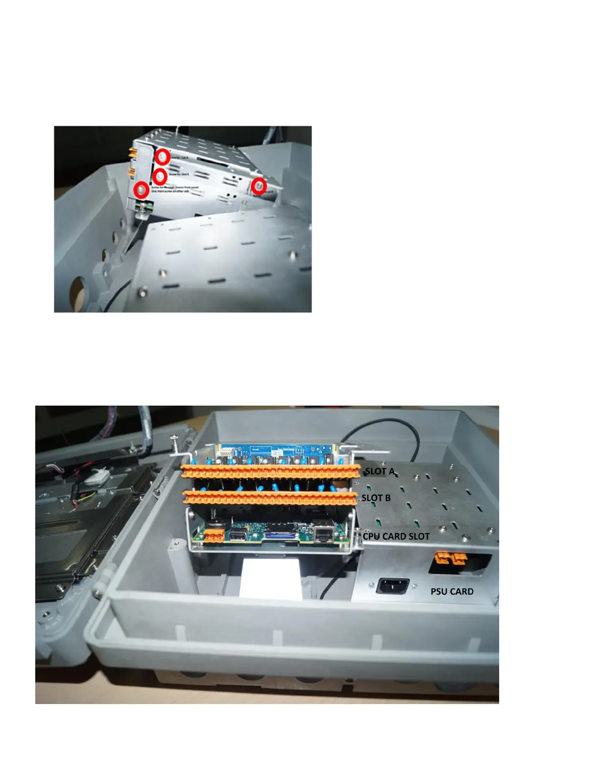
6. For installing the new card in an empty slot (A or B or both), remove the front panel screws.
See Figure 20.
For replacing cards in Slot A, remove both the front panel screws along with the Slot A screw.
For replacing card in Slot B, remove both the front panel screws along with the Slot B screw.
For replacing cards in Slot A and Slot B, remove both the front panel screws along with the screws for Slot A and
Slot B.
Inside the IO Cards Chassis
Refer to the table DR Graphic cards for the correct slot position for the Analogue In / Analogue Out / Pulse Input cards /
Alarm Relay and Digital Input / Output cards. (Note, Slot A cannot have Analogue out, DI/DO & Alarm cards fitted.)

 Loading...