ML7295E DAMPER ACTUATORS
EN0B-099GE02 R1298 2
OPERATION / FUNCTIONS
Rotary Movement
1) Left or right direction of rotation by choosing the
right side of the damper actuator body.
2) If the power supply switched on, the actuator will follow the
output signal of the controller.
3) Nominal torque of 16Nm for damper areas up to 3m
2
.
Spring return
1) In a section of a ventilation plant, for having a safe
closing by spring return in case of power failure. The return
spring will turn the actuator back to 0
°
direction of rotation.
2) Preload tension of 5
°
for a safe closing.
Position indication
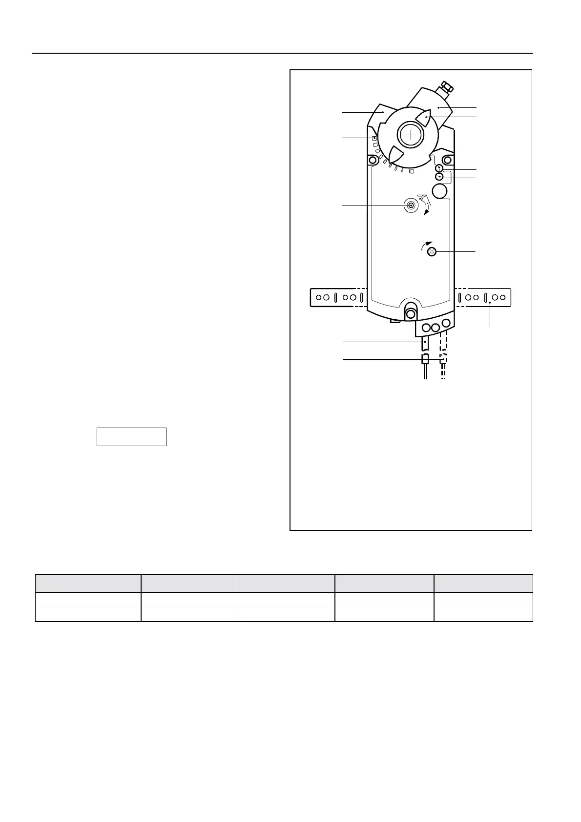
1) The position indicator (Fig. 1., Pos. 3), which is pinned
up on the actuator hub, shows the angle of rotation (11).
2) This actuator provides an electronic feedback signal (2 to
10Vdc). This feedback signal provides indication of the
motor output hub position.
Manual adjustment
The actuator can be turned in any rotary position by an
hexagon socket wrench (in the scope of the equipment)
and locked by a screwdriver. To unlock just by screwdriver
or connect the actuator with the power supply.
Limitation of angular rotation
The angular of rotation can be set between 0
°
and 90
°
in
adjustment steps of 5
°
.
Auxiliary switches
The switching points of the auxiliary switches A and B can
be set independent of each other in the range of the an-
gular of rotation in adjustment steps of 5
°
.
CAUTION
NOTE
These type of actuators must be ordered with or without
auxiliary switches. The integration of these switches
afterwards is impossible.
Type range
Order Number Control Signal Cable length Auxiliary switches Output signal
ML7295E1007 0 to 10Vdc 0.9m - 0 to 10Vdc
ML7295E1015 0 to 10Vdc 0.9m 2 0 to 10Vdc
613Z14
A
B
STOP
2
3
6
0
1
7
4
5
0°
- 5°
1 Housing
2 Self centering shaft coupling
3 Position indicator
4,5 Axis for auxiliary switches
6 Lock axis for the gear mechanism
7 Torsional protection
8 Connecting cable for auxiliary switches
9 Connecting cable for power supply, signal input
and feedback signal
10 Keyhole for manual adjustment
11 Printed angular of rotation
Fig. 1. Setting units and control elements

 Loading...


