ML7295E DAMPER ACTUATORS
3 EN0B-099GE02 R1298
INSTALLATION
The actuator is designed for dual point mounting/installation.
The mounting instructions are enclosed with the actuator.
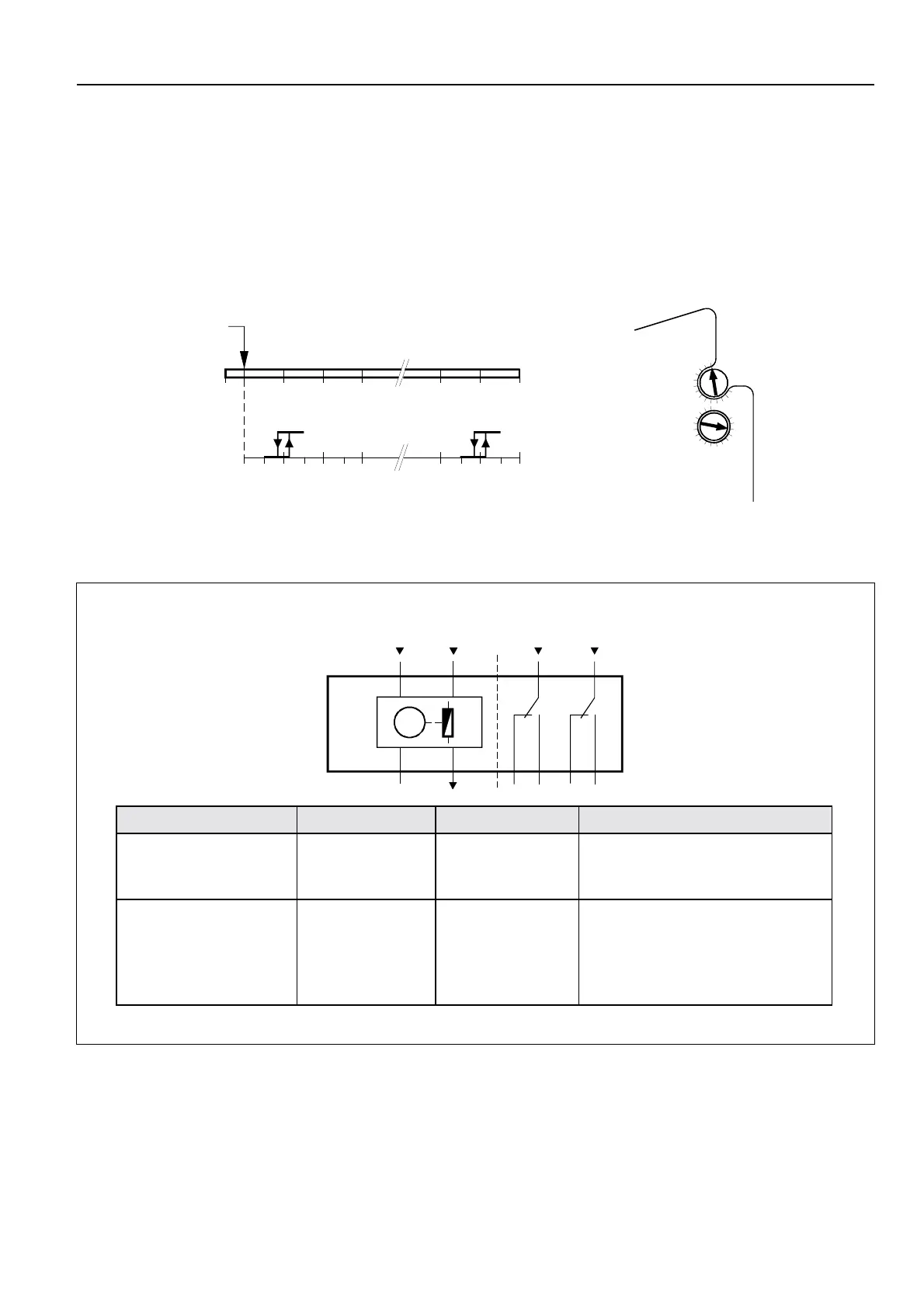
Auxiliary switches (see type range
)
1) The figure below shows the relation between the adjust-
able switching point and the angular of rotation.
2) The axis of the auxiliary switches are rotating if the actua-
tor is in motion. The printed scales are only usable if the
actuator is in position 0
°
.
WIRING
M
A
100%
0%
(L)
(Y)
(N)
(U)
24
S2 S3 S5 S6
1 3 S1 S4
B
AB
-5° 0° 10° 20° 30° 70° 80° 90°
0° 10° 20° 30° 70° 80° 90°
4637D03
Position for self centering
shaft coupling
Printed angular of rotation
Adjustable steps 5
°,
Hysteresis 2
°
Auxiliary switches
setting range
80
70
60
50
B
90
Aux Switch
Adjustment
20
30
40
10
20
40
A
70
4637Z07
Connecting cable for No. Colour Name
Supply and signal lines
1
2
3
4
red
black
gray
pink
24Vac
24Vac ground
Input 0...10Vdc
Position indicator 2...10Vdc
Auxiliary switches
(only ML7295E1015)
S1
S2
S3
S4
S5
S6
grey / red
grey / blue
grey / pink
black / red
black / blue
black / pink
Switch A(12
°
) input
Switch A(12
°
) normally closed
Switch A(12
°
) normally open
Switch B(82
°
) input
Switch B(82
°
) normally closed
Switch B(82
°
) normally open

 Loading...


