EasyManua.ls Logo

Honeywell ML7421A User Manual

Honeywell ML7421A
8 pages
To Next Page IconTo Next Page
Page #1 background imageLoading...
Page #1 background image
PRODUCT DATA
® U.S. Registered Trademark
Copyright © 1996 Honeywell Inc. • All Rights Reserved
X-XX UL 63-2517-1
ML7421A,B
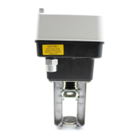
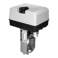
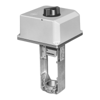
Electric Linear Valve Actuator
APPLICATION
The ML7421A,B Electric Linear Valve Actuators are
modulating control motors for use with low-voltage controls
that provide an analog output of 0 to 10 Vdc or 2 to 10 Vdc.
These actuators operate standard Honeywell valves in
heating, ventilating, and air conditioning (HVAC) applications.
FEATURES
Quick and easy installation.
No separate linkage required.
3/4 in. (20 mm) stroke on ML7421A;
1-1/2 in. (38 mm) stroke on ML7421B.
No adjustments required.
Accurate valve positioning.
Low power consumption.
High close-off ratings.
Force-limiting end switches.
Manual operator.
Synchronous motor.
Corrosion-resistant design.
Maintenance free.
Conduit connector knockout.
Contents
Application .......................................................................... 1
Features .............................................................................. 1
Specifications ...................................................................... 2
Ordering Information ........................................................... 2
Installation ........................................................................... 3
Operation ............................................................................ 6
Checkout ............................................................................. 7
Question and Answer IconNeed help?

Do you have a question about the Honeywell ML7421A and is the answer not in the manual?

Honeywell ML7421A Specifications

General IconGeneral
TypeElectric Actuator
Control Signal2-10 VDC or 4-20 mA
Fail-Safe ModeSpring Return
Number of Outputs1
Mounting TypeDirect Mounting
Input Voltage24 VAC/VDC
Operating Temperature Range-20°C to +60°C
Input SignalVoltage
Stroke90 degrees

Summary

Application

Features

Specifications

Ordering Information

Installation

Location

Specifies the recommended placement of the actuator for optimal installation and servicing.

Mounting

Details the procedure for physically attaching the actuator to the valve collar using set screws.

Wiring

Provides instructions and diagrams for connecting power and control signals to the actuator terminals.

Operation

General

Explains the basic mechanical principle of converting motor rotation to linear stem motion using a worm gear.

Manual Operation

Describes how to operate the valve manually using the built-in knob, including safety precautions.

Signal Input Failure

Outlines how to configure the actuator's behavior during control signal loss using coding switches.

Actuator Override

Explains how to force the actuator to a specific position, bypassing the normal control signal, for applications like freeze protection.

Direction of Action

Details how to change the actuator's response to the control signal (extend/retract) using a selector switch or signal reversal.

Checkout

Direct Checkout

Describes how to test the actuator's functionality directly without a controller, verifying valve position and signal application.

Controller Checkout

Explains how to verify actuator operation when connected to a controller, checking setpoint response and wiring.
Related product manuals