3 NM SERIES SPRING RETURN DIRECT COUPLED ACTUATORS
31-00141M—06 2
Humidity Ratings:
5% to 95% R.H., Non-Condensing
Auxiliary Switches (Two SPST):
Fixed switches on 10 and 80 degrees
125 VAC, 1A, res. load
Mounting: Self-Centering Shaft Adapter (shaft cou-
pling):
Round damper shafts: 3/8 to 5/8 in. (9 to 16 mm)
Square damper shafts: 1/4 to 1/2 in. (6 to 13 mm)
Nominal tightening torque for self-centering shaft
adapter screw is 106 lb-in (12Nm).
Mounting: Non Self-Centering Shaft Adapter:
Round damper shafts: 1/4 to 3/4 in. (6 to 19 mm)
Square damper shafts: 1/4 to 1/2 in. (6 to 13 mm)
Nominal tightening torque for non self-centering shaft
adapter screws is 62 lb-in (7 Nm)
Minimum Damper Shaft Length:
3.25 in. (83 mm) recommended for self-centering shaft
adapter
3 in. (75 mm) recommended for non self-centering
shaft adapter
Spring Return Timing (at rated load):
< 25 seconds @ -22°F to 150°F (-30°C to 65°C)
< 60 seconds @ -40°F to -22°F (-40°C to -30°C)
Cable Specification:
Power Cable: Plenum Rated, 3 ft (0.914 m) length from
end of access cover, 18 AWG
Switch Cable: Appliance Rated, 3 ft (0.914 m) length
from end of access cover, 18 AWG
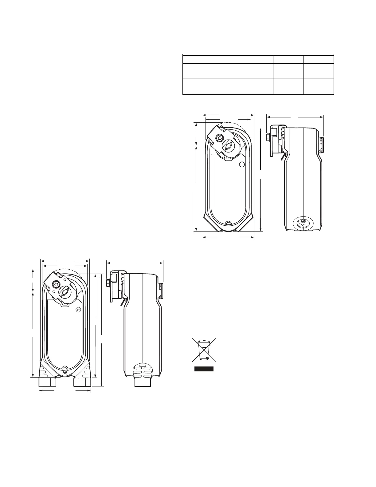
Fig. 1. Dimensional drawing of actuator in in. (mm).
See Table 2 for A and B dimensions.
1
For 1/2” shaft.
Fig. 2. Dimensional drawing of actuator without conduit
in in. (mm). See Table 2 for A and B dimensions.
Stroke:
95° ±3°, mechanically limited.
Approvals:
UL60730
IEC 60730-1 and Part 2–14
UL1097 for Double Insulation
CE Certification Low Voltage Directive 2014/35/EU
CE EMC 2004/108/EC
Switch cables are UL certified only
Waste Electrical and Electronic Equipment (WEEE):
Correct disposal of this product (applicable
in the European Union and other European
countries with separate collection systems).
This product should be disposed of, at the
end of its useful life, as per applicable local
laws, regulations, and procedures.
Enclosure Ratings:
IP54, depends on position according to “Determine
Appropriate Mounting Orientation” on page 3.
NEMA 2
Flame Resistance UL94-5VA
UL2043, switch wiring dependent on conduit
installation
Input Impedance:
95 kOhm minimum for analog modulating input.
Feedback Signal:
2-10 VDC, 1 mA source, 0.5 mA sink
M37461
2-7/8 (72)
B
3-17/64 (83)
6-1/2
(164)
7
(179)
A
5-3/8
(137)
3-1/8 (78)
Table 2. Shaft Adapters.
Type of Shaft Adapter A B
Self-Centering Adapter
3.54 in.
(90 mm)
1.54 in.
(39 mm)
Non Self-Centering Adapter
3.11 in.
(79 mm)
1.57 in.
1
(40 mm)
M37351
2-7/8 (72)
B
3-17/64 (83)
6-1/2
(164)
A
5-3/8
(137)
3-1/8 (78)
 Loading...