10 Mass Notification — P/N LS10063-000NF-E:E 06/26/2019
Configurations Local Operating Console (LOC)
2.2 Local Operating Console (LOC)
2.2.1 Description
A Local Operating Console (LOC) is used by authorized personnel to initiate messages and signaling for mass-notification applications.
It provides three paging levels - Level 1, Level 2 and Level 3 - which may be assigned to MN, fire, or general paging for prioritization
based on site-specific requirements. A page at the MN level will create a latching MN alarm condition that requires acknowledgment and
reset. The LOC supports All Call when priority allows. LOC pages must be ALL CALL pages.
MN events can be acknowledged, silenced or reset only by an active MN command center. When an LOC gains control of acknowledge,
silence and reset functions in an MN system, control is indicated by a lit Controls Active LED at the LOC. All other Controls Active
LEDs in the system are extinguished, red lockout icons appear in ONYXWorks Workstations paging zones and on the acknowledge,
silence, and reset control buttons; acknowledge, silence and reset functions are blocked until the MN alarm is cleared.
Multiple LOC stations can be used in a single system: control is granted on a first-come, first-served basis.
Each LOC requires a point to be mapped in programming, which should be visible when required at the ACU.
2.2.2 Configurations
Either of the following two equipment combinations can meet the requirements for LOC functionality in an MN system when combined
with MN priority programming:
• A DVC-RPU combined with an LCD-160 that is connected to an NC
A-2 or NFS2-3030 (in network display mode).
– The NCA-2 or NFS2-3030 (in network display mode) must be associated through programming with the DVC-RPU’s DVC.
– The DVC-RPU must have the same address on the DAL (Digital Audio Loop) as the LCD-160 has on its RDP bus. Addressing
is critical - refer to page 33 for more information.
• A DVC operated in LOC mode combined with an NFS2-3030 (in network display mode), or NCA-2.
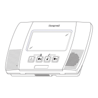
LOC Configuration 1
Figure 2.2 LOC Configurations
LOC Configuration 2
DVC-RPU
NCA-2 or NFS2-
3030, and DVC
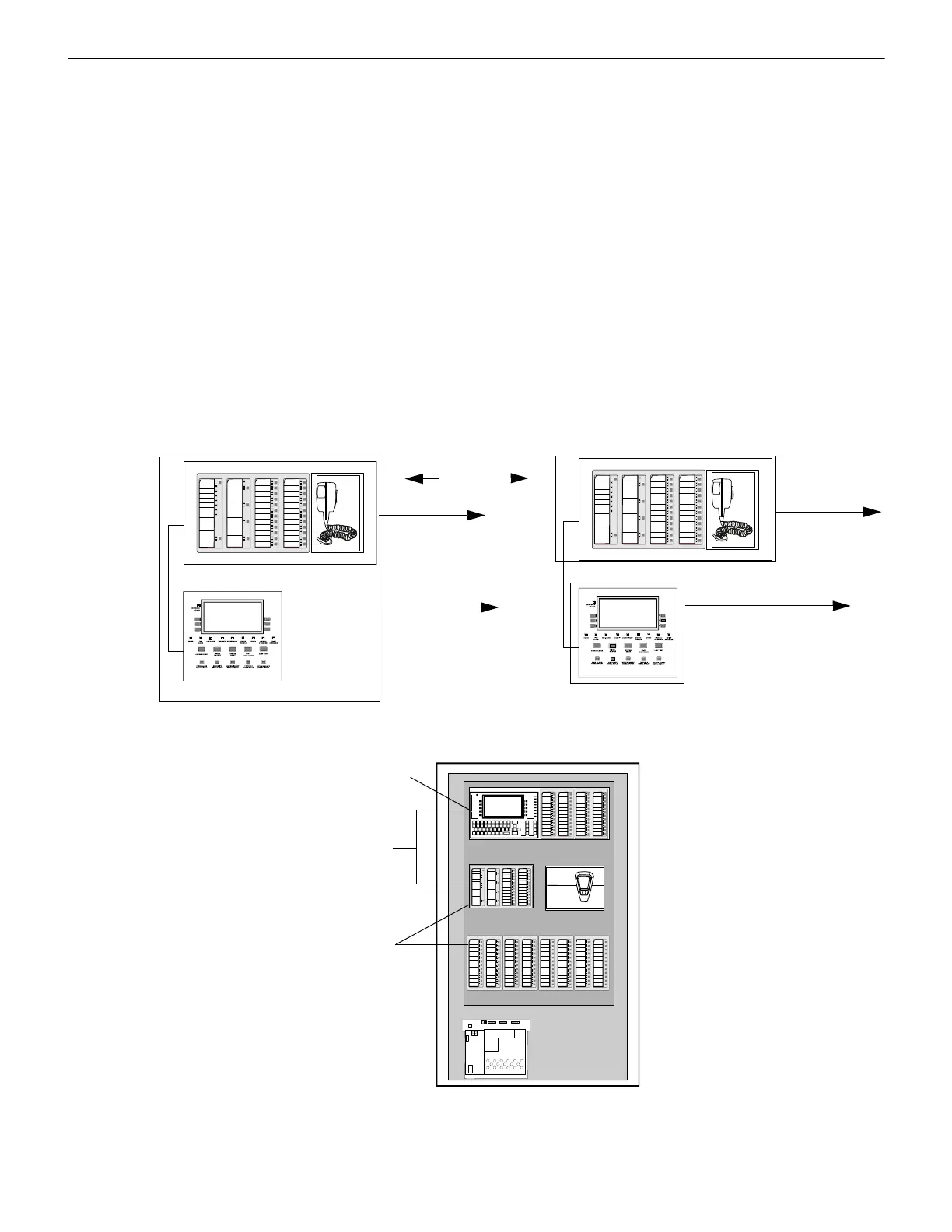
Required LED
annunciator or DVC-KD
point programmed to
illuminate when an MN
alarm activates.
OTHER EVENT LED
for MN alarm
annunciation
RDP bus to NCA-2 or NFS2-
3030 associated through
programming to the DVC-
RPU’s DVC.
LCD-160
DVC-RPU
LCD-160
RDP bus to NCA-2 or NFS2-3030
associated through programming to the
DVC-RPU’s DVC.
OR
Caution!
Addressing is critical to command operations.
The DVC-RPU address on the digital audio loop must equal the LCD-160 address on the RDP bus.
DAL to DVC
DAL to DVC
Refer to Section 3 on page 15 for programming.
 Loading...