2 I56-3500-009
6/23/2021
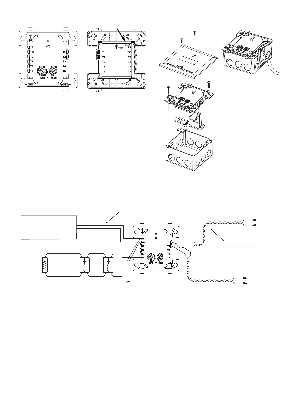
FIGURE 3. TYPICAL NOTIFICATION APPLIANCE CIRCUIT CONFIGURATION, NFPA CLASS B
(+)
(+)
(+)
47K EOL
resistor
ELR-47K
24 VDC CIRCUIT
Do not loop wire on Terminals 10 & 11.
Break wire run to provide supervision of connections.
To next control module or to end-of-line
resistor. See panel manual for resistor values.
REMOVE J1 IN THIS CONFIGURATION.
24 VDC NAC output —
Listed, regulated,
power-limited per NFPA 70,
reverse polarity, switched
Power and NAC polarities are shown in alarm.
CONTROL
MODULE
(–)
(–)
(–)
(+)
(–)
(+)
(–)
(+)
(–)
All wiring shown is supervised and power limited.
To next
device
Signaling Line Circuit (SLC)
32 VDC max
Twisted-pair wire is
recommended.
From panel
or previous
device
Connect modules to listed
compatible control panels only.
NOTE 1: Any fault on Terminals T7 and T8 is limited to that zone and does not result in a fault on another zone when multiple control modules
are interconnected.
NOTE 2: For multiple control modules to serve more than one notification zone, 24 VDC reverse polarity NAC output wiring to T10 & T11 must
be within 20ft in conduit, and wiring of T10 and T11 between control modules must be mechanically protected.
C1017-01
C1070-00
FIGURE 2A. MODULE MOUNTING FIGURE 2B
WITH BARRIER
FIGURE 1A. FIGURE 1B. JUMPER LOCATION
C1059-00 C0910-00

 Loading...


