Do you have a question about the Honeywell NOTIFIER LDM Series and is the answer not in the manual?
Provides an overview of the manual's content and purpose.
Details compliance with UL 864 standards for fire alarm equipment.
Lists other relevant manuals for compatible equipment.
Describes the LDM Series Lamp Driver Modules and their function.
Details the features and specifications of the LDM-32 module.
Details the features and specifications of the LDM-E32 expander module.
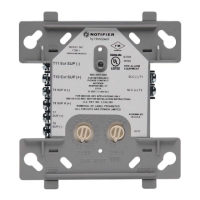
Identifies and describes the connectors on the LDM modules.
Explains the function of various DIP and mode switches on the modules.
Describes the terminal blocks for power, ground, and supervision inputs.
Lists and describes the types of cables used for LDM module connections.
Details the LDM-R32 Relay Expander Module and its capabilities.
Step-by-step guide for installing LDM modules in cabinets or chassis.
Information on suitable external cabinets for graphic annunciators.
Details the CHS-4L chassis for mounting LDM modules.
Defines the maximum number of LDM-32s and system constraints.
Specifies requirements for wire runs and communications.
Provides detailed specifications for EIA-485 wiring.
Explains how to terminate EIA-485 shields when using conduit.
Explains how to terminate EIA-485 shields when not using conduit.
Covers EIA-485, power, and relay wiring connections.
Details the supervision input for monitoring external devices.
Outlines UL requirements for power-limited wiring.
Provides guidance on wiring LEDs and lamps to the LDM modules.
Explains how to wire optional zone/point control switches.
Describes the function of the LAMP TEST/ACKNOWLEDGE switch.
Explains the function of the green ON LINE LED.
Details the color convention for status indication on graphic annunciators.
Configuration for LDMs to receive but not transmit information.
Configuration for LDMs to receive and transmit system information.
Lists electrical ratings and power limitations for LED drivers.
Explains that LDM points and LEDs are not supervised for failure.
Guides on calculating standby and alarm current draws.
Details the capabilities of LDM Series modules with System 500.
Describes trouble indications within the System 500.
Specifies installation requirements for System 500 integration.
Details the MPS-24BPCC power supply for System 500.
Explains DIP switch settings for System 500 configurations.
Describes how annunciators operate with the System 500.
Details the capabilities of LDM Series modules with System 5000.
Specifies installation requirements for System 5000 integration.
Details the MPS-24A power supply for System 5000.
Details the MPS-24B power supply for System 5000.
Explains DIP switch settings for System 5000 configurations.
Describes AIM-200 module annunciation with System 5000.
Lists capabilities when using LDM with specific Notifier panels.
Identifies devices compatible with LDM modules.
Specifies required software versions for compatibility.
Details connections for NFS2-3030, NCA-2, and NFS-3030 panels.
Explains specific connection details for NCA panels.
Details specific connection requirements for AM2020/AFP1010.
Guides on programming LDM points for these panels.
Describes how LDM points track system events.
Details DIP switch configuration for various panel types.
Provides specific wiring instructions for these panel types.
Lists capabilities when using LDM with an AFP-100.
Describes how lamp driver outputs operate on the AFP-100.
Guides on programming LDM for remote annunciation.
Specifies installation requirements for AFP-100 integration.
Details DIP switch configuration for AFP-100.
Lists capabilities when using LDM with an AFP-200.
Describes trouble indications within the AFP-200.
Describes how lamp driver outputs operate on the AFP-200.
Guides on programming LDM for remote annunciation.
Specifies installation requirements for AFP-200 integration.
Details DIP switch configuration for AFP-200.
Lists capabilities when using LDM with these Notifier panels.
Guides on programming LDM points for these panels.
Details connections for NFS2-640 and NFS-320 panels.
Details specific connection requirements for AFP-300/400.
Details specific connection requirements for NFS-640.
Lists capabilities when using LDM with an SFP-1024.
| Model | LDM Series |
|---|---|
| Humidity Range | 10% to 93% non-condensing |
| Communication Protocol | Notifier Protocol |
| Operating Voltage | 24 VDC nominal |
| Operating Temperature | 0°C to 49°C (32°F to 120°F) |
| Mounting | Surface |
| Compatibility | Compatible with Notifier fire alarm control panels |