60 LDM Series Instruction Manual — P/N 15885:H3 8/12/2019
AFP-200 (UL 8th) Configuration for the LDM-32 and AFP-200
E.6 Configuration for the LDM-32 and AFP-200
LDM-32 DIP Switch (SW3) settings (for AFP-200):
1. Relay Control: Future Use - this switch must be set OFF on the AFP-200.
NoneOneTwoThree
2. Number of LDM-E32 Expanders Installed:OFFONOFFON
3. Number of LDM-E32 Expanders Installed:OFFOFFONON
4. 8-Point Shift: Set switch ON to shift AFP-200 LED function annunciation from the first eight annunciator positions on the
LDM-32 to the third LDM-E32 expander positions 57 - 64. This shift can only be set on an LDM-32 set for address 1 (system using
less than 56 software zones).
5. Receive Only: Set this switch ON for each LDM series that will provide the same information as another LDM series in a different
physical location (when two or more sets of LDM series have the same address, all but one must be configured as Receive Only.)
6. Piezo Disable: Set this switch ON to disable the piezo from sounding for any event.
7. Switch Inhibit: To disable the point I/O control switches on the LDMs from functioning, set this switch ON. When inhibited, the
switches will serve as local Lamp Test switches only. In addition, the Acknowledge/Lamp Test switch will function only in a local
capacity, unrecognized by the host AFP-200.
8. Flash Inhibit: Set this switch ON to disable the flashing of LEDs associated with unacknowledged events. Flash Inhibit also
disables the piezo from sounding. Flash inhibit must be ON when using the relay expander module (LDM-R32).
Alarm and Trouble Mode Without 8-Point Shift
A second LDM-32 set to address 02 with expanders would not support control switches.
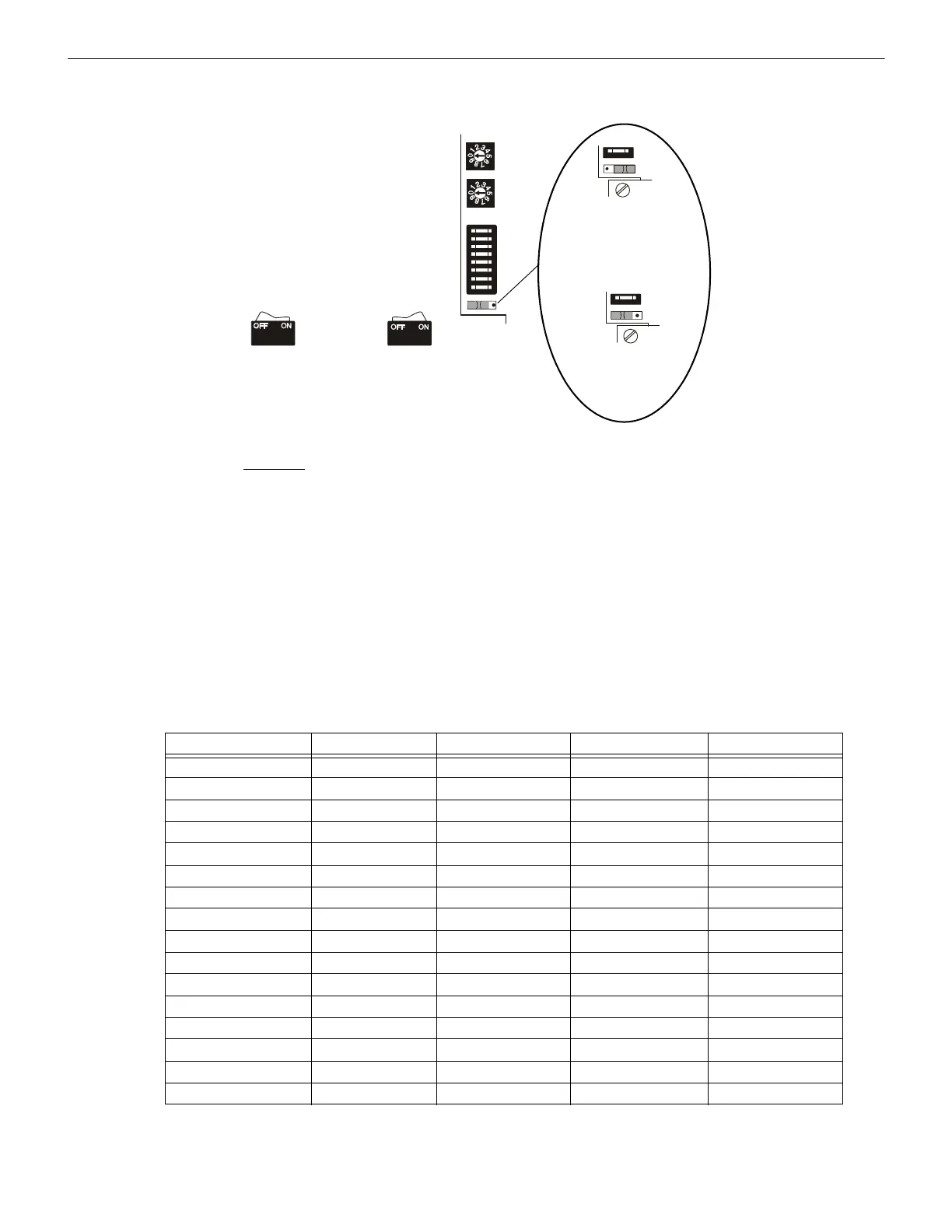
LDM-32
Switch set to
ON position
Switch set to
OFF position
Lamp Driver Address
Set in the range 01 or 02
Ones
Tens
DIP Switch SW3
(see settings below)
Lamp Driver Mode Switch
SW4
SW4
ALARM/TROUBLE mode
(SW4 set to right side)
ALARM ONLY mode
(SW4 set to left side)
LDM Switch Position LDM-32 1st LDM-E32 2nd LDM-E32 3rd LDM-E32
1 ACK not used not used not used
2 SIG.SIL. not used not used not used
3 RESET not used not used not used
4 DRILL not used not used not used
5 not used not used not used not used
6 not used not used not used not used
7 not used not used not used not used
8 not used not used not used not used
9 not used not used not used not used
10 not used not used not used not used
11 not used not used not used not used
12 not used not used not used not used
13 not used not used not used not used
14 not used not used not used not used
15 not used not used not used not used
16 not used not used not used not used

 Loading...


