46 LDM Series Instruction Manual — P/N 15885:H3 8/12/2019
NFS2-3030 and NCA-2 (UL 9th), AM2020/AFP1010, NFS-3030, or NCA (UL 8th) Annunciator Programming
C.7 Annunciator Programming
LDM points must be programmed from the FACP before the LDM will function. The NFS2-3030, NFS-3030, NCA-2, NCA and
AM2020/AFP1010 employ the following format for annunciator points:
For programming the Lamp Driver Series into the FACP or network annunciator’s memory, and for mapping system points and software
zones to annunciator points, refer to the appropriate FACP/network annunciator documents referenced in Section 1.3, “Related Docu-
mentation”, on page 7. In the NFS2-3030, NFS-3030, NCA-2, and NCA documentation, refer to the sections about ACS Programming
and ACS Point Programming. In AM2020/AFP1010 documentation, refer to the sections about Programming for Remote Annunciation.
C.8 Operation
LDM points 'track' or follow those system points they are programmed to annunciate; the points do not latch unless latched by the panel.
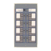
Table C.1 is a list of how the LDM-32 annunciates various AM2020/AFP1010 devices and functions; all functions are the same for NFS-
3030/NFS2-3030/NCA/NCA-2. Note: Control Switches marked 'not used' will still function as local LAMP TEST switches for their
respective LEDs.
For more information on LDM operation and FACP programming under various specific applications, refer to the appropriate FACP/net-
work annunciator documents referenced in Section 1.3, “Related Documentation”, on page 7.
A(xx) P(yy)
LDM (Annunciator) address
is the range of 1-32, as set on the
annunciator’s rotary decimal switches.
LDM (Annunciator) point
LDM Alarm/Trouble Mode:
LDM Alarm Only Mode:
LDM-32
points 1-16
LDM-32
points 1-32
1st LDM-E32
points 17-32
1st LDM-E32
points 33-64
2nd LDM-E32
points 38-48
3rd LDM-E32
points 49-64
Point Type
Alarm and Trouble Mode
Alarm Mode Only
Red LED Yellow LED Control Switch
Control Module
XPC Circuit
XPR Circuit
Indicates on/off status
of module or circuit
Indicates trouble/
supervisory status of
module or circuit
Turn module on/off
Monitor Module
XPM Circuit
Indicates active status
of module or circuit
Indicates trouble/
supervisory status of
module or circuit
not used
Intelligent Detector Indicates fire alarm
status of detector
Indicates trouble
status of detector
not used
Software Zone Indicates active status
of software zone
Indicates trouble/
supervisory status of
software zone
not used
ACK/STEP key Indicates Fire Alarm Indicates System
Trouble
Functions as an
ACK/STEP key
SIGNAL SILENCE
key
not used Indicates Signals
Silenced
Functions as a SIGNAL
SILENCE key
SYSTEM RESET
key
Indicates Fire Alarm Indicates System
Trouble
Functions as a
SYSTEM RESET key
LAMP TEST key not used not used Functions as a LAMP
TEST key
Table C.1 Lamp Driver Point Functions
 Loading...

