EasyManua.ls Logo

Honeywell Notifier XP6-R - User Manual

Honeywell Notifier XP6-R
4 pages
Print Icon
To Next Page IconTo Next Page
Loading...
N500-78-00 1 I56-1804-012
BEFORE INSTALLING
If the modules will be installed in an existing operational system, inform the
operator and local authority that the system will be temporarily out of service.
Disconnect the power to the control panel before installing the modules. This
system contains static sensitive components. Always ground yourself with a
proper wrist strap before handling any circuits so that static charges are re-
moved from the body. The housing cabinet should be metallic and suitably
grounded.
NOTICE: This manual should be left with the owner/user of this equipment.
GENERAL DESCRIPTION
The XP6-R Six Relay Control Module is intended for use in an intelligent alarm
system. Each module is intended for Form-C switching applications, which
do not require wiring supervision for the load circuit. A single isolated set
of dry relay contacts is provided for each module, which is capable of being
wired for either normally open or normally closed for each operation. Each
module has its own address. A pair of rotary code switches is used to set the
address of the first module from 01 to 154. The remaining modules are auto-
matically assigned to the next five higher addresses. Provisions are included
for disabling a maximum of three unused modules to release the addresses to
be used elsewhere. Each XP6-R module also has panel controlled green LED
indicators. The panel can cause the LEDs to blink, latch on, or latch off.
XP6-R Six Relay Control Module
SPECIFICATIONS
Normal Operating Voltage: 15-32VDC
Stand-By Current: 1.90 mA @ 24V
Alarm Current: 32 mA (assumes all six relays have been switched once and all six LEDs solid on)
Temperature Range: 32°F to 120°F (0°C to 49°C)
Humidity: 10 to 93% Non-condensing
Dimensions: 6.8˝H × 5.8˝W × 1.0˝D
Accessories: CHS-6 Chassis; BB-25 Cabinet; BB-XP Cabinet; CAB-3 Series Cabinets; CAB-4 Series Cabinets
Wire Gauge: 12-18 AWG
Relay Current: 30 mA/Relay Pulse (15.6 mS pulse duration) pulse under panel control
CONTENTS INCLUDE:
(6) 1 × 3 Terminal Blocks
(1) 1 × 4 Terminal Blocks
(2) 11/4˝ (32mm) Stand offs
(4) Machine Screws
(2) Nuts
(1) Shunt (NOTE: For the disable position, not more than one shunt shall be
installed at the same time)
COMPATIBILITY REQUIREMENTS
To ensure proper operation, this module shall be connected to a compatible
Notifier system control panel.
COMPONENTS
Following are descriptions of the XP6-R mounting frameworks. There are two
mounting options for XP6-R modules:
Up to six XP6-R modules can be installed on a CHS-6 in a CAB-3, CAB-4
or BB-25 cabinet
One or two XP6-R modules can be installed in a BB-XP cabinet
Chassis
The CHS-6 chassis is used to mount XP6-R modules in a BB-25, CAB-3 or
CAB-4 Series cabinet. It accommodates up to six XP6-R modules in a single
cabinet row three modules wide and two modules deep.
WARNING
All relay switch contacts are shipped in the standby state (open) state, but may have transferred to the activated (closed) state during shipping. To ensure that
the switch contacts are in their correct state, modules must be made to communicate with the panel before connecting circuits controlled by the module.
I56-1804-012
RELAY CONTACT RATINGS:
12 Clintonville Road
Northford, CT 06472-1653
Phone: 203.484.7161
INSTALLATION AND MAINTENANCE INSTRUCTIONS
CURRENT RATING MAXIMUM VOLTAGE LOAD DESCRIPTION APPLICATION
2 A 25 VAC PF = 0.35 Non-coded
3 A 30 VDC Resistive Non-coded
2 A 30 VDC Resistive Coded
0.46 A 30 VDC (L/R = 20ms) Non-coded
0.7 A 70.7 VAC PF = 0.35 Non-coded
0.9 A 125 VDC Resistive Non-coded
0.5 A 125 VAC PF = 0.75 Non-coded
0.3 A 125 VAC PF = 0.35 Non-coded
Question and Answer IconNeed help?

Do you have a question about the Honeywell Notifier XP6-R and is the answer not in the manual?

Summary

XP6-R Six Relay Control Module Specifications

Normal Operating Voltage

Specifies the normal operating voltage range for the XP6-R module.

Stand-By Current

Indicates the current draw when the module is in standby mode.

Alarm Current

Details the current draw when the module is in alarm state.

Temperature Range

Defines the operational temperature limits for the module.

Humidity

Specifies the acceptable humidity levels for operation.

Dimensions

Provides the physical size of the XP6-R module.

Accessories

Lists compatible chassis and cabinets for the module.

Wire Gauge

Indicates the recommended wire gauge for connections.

Relay Contact Ratings

Details the current and voltage ratings for the relay contacts.

Installation and Configuration

Before Installing

Provides essential precautions and steps before module installation.

General Description

Describes the XP6-R module's purpose and functionality in alarm systems.

Compatibility Requirements

Outlines the necessary system compatibility for the module.

Components and Chassis

Details the XP6-R module's mounting frameworks and chassis.

Chassis Installation

Instructions for mounting the CHS-6 chassis in various cabinets.

Module Installation Methods

Describes two methods for installing modules in chassis slots.

Wiring and Addressing

Wiring Notes

Important notes regarding wiring practices and safety.

Electrical Connections

Details on making electrical connections for module wiring.

Address Setting

Instructions for setting module addresses using rotary switches.

Extended Addressing

Notes on setting module addresses above 99 on compatible systems.

Address Disable Shunt

Information on using shunts to disable unused modules.

Programming and Compliance

Compatible Control Panels

Lists Fire Alarm Control Panels compatible with the XP6-R module.

Programming Procedure

Details how modules are programmed within FACP systems.

FCC Statement

Compliance statement regarding radio frequency interference.

Overview

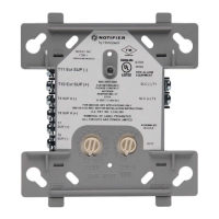
The XP6-R Six Relay Control Module is an intelligent alarm system component designed for Form-C switching applications. Each module provides a single isolated set of dry relay contacts, configurable for either normally open or normally closed operation, and does not require wiring supervision for the load circuit. It features individual addressing, set by a pair of rotary code switches for the first module (addresses 01 to 154), with subsequent modules automatically assigned the next five higher addresses. The module also includes panel-controlled green LED indicators that can blink, latch on, or latch off.

Function Description:

The XP6-R module allows for the control of up to six independent relays within an intelligent fire alarm system. These relays can be used for various switching applications, such as controlling auxiliary devices, activating notification appliances, or interfacing with other building systems. The module's intelligent design allows for communication with compatible Notifier control panels, enabling precise control and status monitoring of each relay. A key feature is the ability to disable up to three unused modules, releasing their addresses for use elsewhere. This is achieved by placing a shunt on the "Address Disable" pins, with disabled modules always being the highest addresses in the sequence.

Important Technical Specifications:

  • Normal Operating Voltage: 15-32VDC
  • Stand-By Current: 1.90 mA @ 24V
  • Alarm Current: 32 mA (assuming all six relays are switched and all six LEDs are solid on)
  • Temperature Range: 32°F to 120°F (0°C to 49°C)
  • Humidity: 10 to 93% Non-condensing
  • Dimensions: 6.8"H × 5.8"W × 1.0"D
  • Wire Gauge: 12-18 AWG
  • Relay Current: 30 mA/Relay Pulse (15.6 ms pulse duration) pulse under panel control

Relay Contact Ratings (Maximum Voltage / Current / Load Description / Application):

  • 2 A / 25 VAC / PF = 0.35 / Non-coded
  • 3 A / 30 VDC / Resistive / Non-coded
  • 2 A / 30 VDC / Resistive / Coded
  • 0.46 A / 30 VDC / (L/R = 20ms) / Non-coded
  • 0.7 A / 70.7 VAC / PF = 0.35 / Non-coded
  • 0.9 A / 125 VDC / Resistive / Non-coded
  • 0.5 A / 125 VAC / PF = 0.75 / Non-coded
  • 0.3 A / 125 VAC / PF = 0.35 / Non-coded

Usage Features:

  • Addressing: Each module has a unique address set by rotary code switches. The first module's address can be set from 01 to 154, and subsequent modules are automatically assigned the next five consecutive addresses. Extended addressing above 99 is supported on compatible systems by carefully removing the stop on the upper rotary switch.
  • Module Disabling: A shunt is provided to disable up to three unused modules, starting from the highest address downward. This allows for address optimization in systems where not all six relays are required.
  • LED Indicators: Panel-controlled green LEDs provide visual status feedback, capable of blinking, latching on, or latching off.
  • Mounting Options:
    • Up to six XP6-R modules can be installed on a CHS-6 chassis within a BB-25, CAB-3, or CAB-4 cabinet.
    • One or two XP6-R modules can be installed in a BB-XP cabinet, which has a built-in chassis.
    • The chassis design ensures that the front module positions are offset below the rear positions, making all status indicators visible.
  • Wiring: Relay contacts can be connected to either power-limited or non-power-limited sources. It is crucial to maintain at least 1/4" (6.35 mm) separation between power-limited and non-power-limited wiring. Power-limited circuits must use FPL, FPLR, or FPLP cable as per Article 760 of the NEC.
  • Compatibility: The XP6-R module is compatible with various Notifier Fire Alarm Control Panels, including AM2020/AFP1010, AFP-200, AFP-300/AFP-400, System 5000 with AIM-200, AFC-600, NFS-640, and NFS-3030. Modules are programmed as FRM-1 modules within these systems.

Maintenance Features:

  • Static Sensitivity: The system contains static-sensitive components. Users must ground themselves with a proper wrist strap before handling any circuits to prevent static discharge.
  • Power Cycling: The XP6-R module requires a power cycle for shunt changes (e.g., disabling modules) to take effect.
  • Installation Instructions: Detailed steps are provided for chassis and module installation, including two methods for rear module installation and one for front module installation, ensuring proper alignment and secure fastening.
  • Wiring Diagrams: Installation requires adherence to job drawings and appropriate wiring diagrams, with clear instructions for stripping wire insulation and tightening clamping plate screws.
  • FCC Compliance: The device complies with Part 15 of the FCC Rules, ensuring it does not cause harmful interference and accepts any interference received. Guidelines are provided for resolving potential interference issues, such as reorienting antennas or increasing separation between equipment.

Honeywell Notifier XP6-R Specifications

General IconGeneral
BrandHoneywell
ModelNotifier XP6-R
CategoryControl Unit
LanguageEnglish

Related product manuals