1 I56-3500-009
6/23/2021
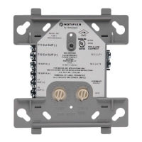
FCM-1 Supervised Control Module
ration of power-limited and nonpower-limited terminals and wiring. The bar-
rier must be inserted into a 4˝ × 4˝ × 2
1
/8˝ junction box, and the control
module must be placed into the barrier and attached to the junction box. (See
Figure 2A.) The power-limited wiring must be placed into the isolated quad-
rant of the module barrier. (See Figure 2B.)
1. Install module wiring in accordance with the job drawings and appropri-
ate wiring diagrams.
2. Set the address on the module per job drawings.
3. Secure module to electrical box (supplied by installer). (See Figure 2A.)
Wire should be stripped to the appropriate length (recommended strip length
is
1
/4˝ to
3
/8˝). Exposed conductor should be secured under the clamping plate
and should not protrude beyond the terminal block area.
CAUTION: Do not loop wire under terminals. Break wire run to provide su-
pervision of connections.
IMPORTANT: When using the FCM-1 for audio applications, remove
Jumper (J1) and discard. The Jumper is located on the back as shown in
Figure 1B.
J1 must be removed whenever power supply monitoring feature is not required.
NOTE: All references to power limited represent “Power Limited (Class 2)”.
All references to Class A also include Class X.
SPECIFICATIONS
Normal Operating Voltage: 15 to 32 VDC
Maximum Current Draw: 6.5 mA (LED on)
Average Operating Current: 375µA (LED flashing - in group poll mode) 350µA (LED flashing - in direct poll mode); 485µA Max. (LED flashing, NAC shorted)
Maximum NAC Line Loss: 4 VDC
External Supply Voltage (between Terminals T10 and T11)
Maximum (NAC): Regulated 24 VDC
Maximum (Speakers): 70.7 V RMS, 50 W
Drain on External Supply: 1.7 mA Maximum using 24 VDC supply; 2.2 mA Maximum using 80 VRMS supply
Max NAC Current Ratings: For class B wiring system, the current rating is 3A; For class A wiring system, the current rating is 2A
Temperature Range: 32°F to 120°F (0°C to 49°C)
Humidity: 10% to 93% Non-condensing
Dimensions: 4.675˝ H x 4.275˝ W x 1.4˝ D (Mounts to a 4˝ square by 2
1
/8˝ deep box.)
Accessories: SMB500 Series Electrical Box; CB500 Barrier
I56-3500-009
INSTALLATION AND MAINTENANCE INSTRUCTIONS
12 Clintonville Road
Northford, CT 06472-1653
Phone: 203.484.7161
RELAY CONTACT RATINGS
CURRENT RATING MAXIMUM VOLTAGE LOAD DESCRIPTION APPLICATION
2 A 25 VAC PF = 0.35 Non-coded
3 A 30 VDC Resistive Non-coded
2 A 30 VDC Resistive, NAC, and Door Holder Coded
0.46 A 30 VDC (L/R = 20ms) Non-coded
0.7 A 70.7 VAC PF = 0.35 Non-coded
0.9 A 125 VDC Resistive Non-coded
0.5 A 125 VAC PF = 0.75 Non-coded
0.3 A 125 VAC PF = 0.35 Non-coded
BEFORE INSTALLING
This information is included as a quick reference installation guide. Refer to
the control panel installation manual for detailed system information. If the
modules will be installed in an existing operational system, inform the opera-
tor and local authority that the system will be temporarily out of service. Dis-
connect power to the control panel before installing the modules.
NOTICE: This manual should be left with the owner/user of this equipment.
GENERAL DESCRIPTION
FCM-1 Supervised Control Modules are intended for use in intelligent, two-
wire systems, where the individual address of each module is selected us-
ing the built-in rotary switches. This module is used to switch an external
power supply, which can be a DC power supply or an audio amplifier (up
to 80 VRMS), to notification appliances. It also supervises the wiring to the
connected loads and reports their status to the panel as NORMAL, OPEN,
or SHORT CIRCUIT. The FCM-1 has two pairs of output termination points
available for fault-tolerant wiring and a panel-controlled LED indicator. This
module can be used to replace a CMX-2 module that has been configured for
supervised wiring operation.
COMPATIBILITY REQUIREMENTS
To ensure proper operation, this module shall be connected to a compatible
Notifier system control panels only (list available from Notifier).
MOUNTING
The FCM-1 mounts directly to 4-inch square electrical boxes. (See Figure 2A.)
The box must have a minimum depth of 2
1
/8 inches. Surface mounted electri-
cal boxes (SMB500 Series) are available. The module can also mount to the
DNR(W) duct housing.
WIRING
NOTE: All wiring must conform to applicable local codes, ordinances, and
regulations. When using control modules in nonpower limited applications,
the CB500 Module Barrier must be used to meet UL requirements for the sepa-