4 I56-3500-009
©2021 Notifier. 6/23/2021
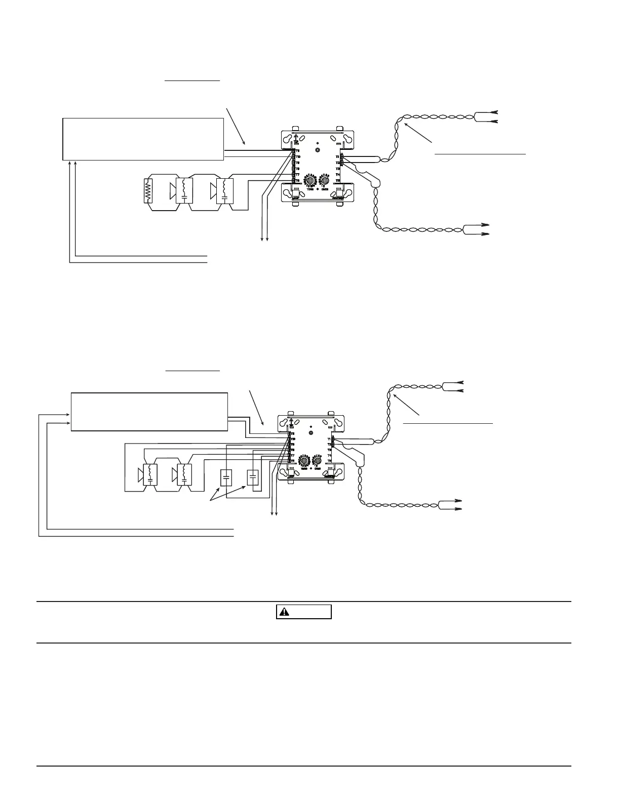
FIGURE 6. TYPICAL WIRING FOR SPEAKER SUPERVISION AND SWITCHING, NFPA CLASS B
(+)
(–)
(+)
(–)
(+)
(–)
(–)
(+)
(–)
(+)
(+)
(–)
AUDIO CIRCUIT
Do not loop wire on Terminals 10 & 11.
Break wire run to provide supervision of connections.
Signaling Line Circuit (SLC)
32 VDC max
Twisted-pair wire is
recommended.
All wiring shown is supervised
and power limited.
Wires must be supervised per NFPA
Connect modules to listed
compatible control panels only.
From panel
or previous
device
CONTROL
MODULE
47K EOL
resistor
ELR-47K
Speakers must be listed
for fire protection.
To next
device
Module polarities are
shown in alarm
To next control module.
Last module must return
wires for supervision.
Supervision
Audio circuit wiring must be twisted pair as a minimum.
See fire alarm system documentation for detailed information.
Audio amplifier, 70.7 Vrms max.
Use only compatible audio amplifiers listed for
fire protection service. Amplifier must provide
wiring supervision per NFPA.
NOTE: Any fault on Terminals T7 and T8 is limited to that zone and does not result in a fault on another zone when multiple control modules
C1016-02
FIGURE 7. TYPICAL FAULT TOLERANT WIRING FOR SPEAKER SUPERVISION AND SWITCHING, NFPA CLASS A
(+)
(–)
(+)
(–)
(+)
(–)
(+)
(–)
(–)
(+)
(–)
(+)
All wiring shown is supervised
and power limited.
To next
device
Signaling Line Circuit (SLC)
32 VDC max
Twisted-pair wire is
recommended.
Wires must be supervised per NFPA
Connect modules to listed
compatible control panels only.
From panel
or previous
device
CONTROL
MODULE
Speakers must be listed
for fire protection.
47K EOL resistor
is internal at
Terminals T8 & T9
Module polarities are
shown in alarm
To next control module.
Last module must return
wires for supervision.
Supervision
Audio circuit wiring must be twisted pair as a minimum.
See fire alarm system documentation for detailed information.
Audio amplifier, 70.7 Vrms max.
Use only compatible audio amplifiers listed for
fire protection service. Amplifier must provide
wiring supervision per NFPA.
AUDIO CIRCUIT
Do not loop wire on Terminals 10 & 11.
Break wire run to provide supervision of connections.
Bypass capacitors: 100µ
A2143-20 non-polarized
<10µA leakage
NOTE: Any fault on Terminals T7 and T8 is limited to that zone and does not result in a fault on another zone when multiple control modules
C1024-03
All relay switch contacts are shipped in the standby state (open) state, but may have transferred to the activated (closed) state during shipping. To ensure that
the switch contacts are in their correct state, modules must be made to communicate with the panel before connecting circuits controlled by the module.
FlashScan
®
, Notifier
®
, System Sensor
®
, and Honeywell
®
are registered trademarks of Honeywell International, Inc.

 Loading...


