EasyManua.ls Logo

Honeywell NETAXS NX4L1 User Manual

Honeywell NETAXS NX4L1
86 pages
To Next Page IconTo Next Page
Page #1 background imageLoading...
Page #1 background image
July 2016 © 2016 Honeywell. All rights reserved. 7-901099V3
Honeywell NetAXS™
NX4L1
Access Control Unit
Installation Guide

Table of Contents

Questions and Answers:

Honeywell NETAXS NX4L1 Specifications

General IconGeneral
ModelNETAXS NX4L1
TypeControl Unit
ManufacturerHoneywell
Number of Doors Supported4
Power Supply12V DC
CommunicationRS-485, TCP/IP
Input Voltage12 VDC
Operating Temperature0°C to +50°C (32°F to +122°F)
CertificationsCE, FCC, UL294

Summary

Notices and Compliance

1.1 Safety and Liability Warnings

Safety and liability notices regarding fire safety, system testing, grounding, and power connections.

1.3 Limited Warranty Terms

Details the warranty terms, conditions, and exclusions for HAS products.

1.4 FCC and Industry Canada Compliance

Equipment compliance with FCC Part 15 Class B digital device requirements.

Introduction to NetAXS

2.1 Access Control System Overview

General explanation of access control systems and their functions.

3.0 Panel Components and Descriptions

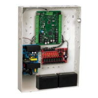
Detailed description of NetAXS panel components, including power and enclosure.

Installation Procedures

4.1 Optional AC Inlet Installation

Instructions for installing the optional AC inlet kit (part number 100-00049).

4.2 NX4L1 Cabinet Field Wiring

Diagram illustrating how to route and tie field wiring within the NX4L1 cabinet.

4.3 Cabinet Mounting Views

Diagrams showing dimensions and knockout placement for cabinet mounting.

4.4 Reader and Input/Output Wiring

Details on reader wiring, supervised inputs, control outputs, and downstream I/O.

4.7 Communications and Network Configurations

Overview of communication methods including RS-232, RS-485, Ethernet, and network setups.

4.8 DIP Switch and Jumper Settings

Location and function of DIP switches and jumpers for panel configuration.

System Configuration and Standalone Operation

5.0 System Configuration Diagrams

Wiring diagrams for various system configurations including RS-485, RS-232, and Ethernet.

6.0 NetAXS Startup and LED Status

Information on panel startup sequence and the meaning of LED indicators.

7.0 Hardware Specifications

Technical specifications for relays, reader interface, output loading, mechanicals, and environment.

8.0 Maintenance Procedures

Instructions for routine maintenance tasks like battery replacement and fuse checks.

9.0 Troubleshooting Guide

Table listing common problems and their solutions for the NetAXS system.

NetAXS Standalone Operation

Details on basic standalone operations, settings, and commands for the NetAXS panel.

Recommended RS-485 Wiring

3.0 RS-485 Wiring for NetAXS-4 Loop

Specific wiring instructions for RS-485 loops using NetAXS-4 controllers.

4.0 RS-485 Wiring for a Mixed Loop

Instructions for RS-485 wiring in mixed loops with NetAXS-123 and NetAXS-4.

5.0 End of Line Termination

Instructions for terminating RS-485 bus controllers (NetAXS-123 and NetAXIS).

Related product manuals