28 www.honeywell.com
NetAXS™ NX4L1 Installation Guide
Installation
4.5 Supervised Input Wiring
The supervised inputs are located on TB4 and TB13 (Figure 8 on page 28). Input 1
through Input 8 may be configured for normally open or normally closed contacts as
supervised or non-supervised. Inputs 13 and 14 are on TB8. All eight inputs have
default functions, but they can be configured for general purpose inputs.
The following table identifies the default function for each terminal position.
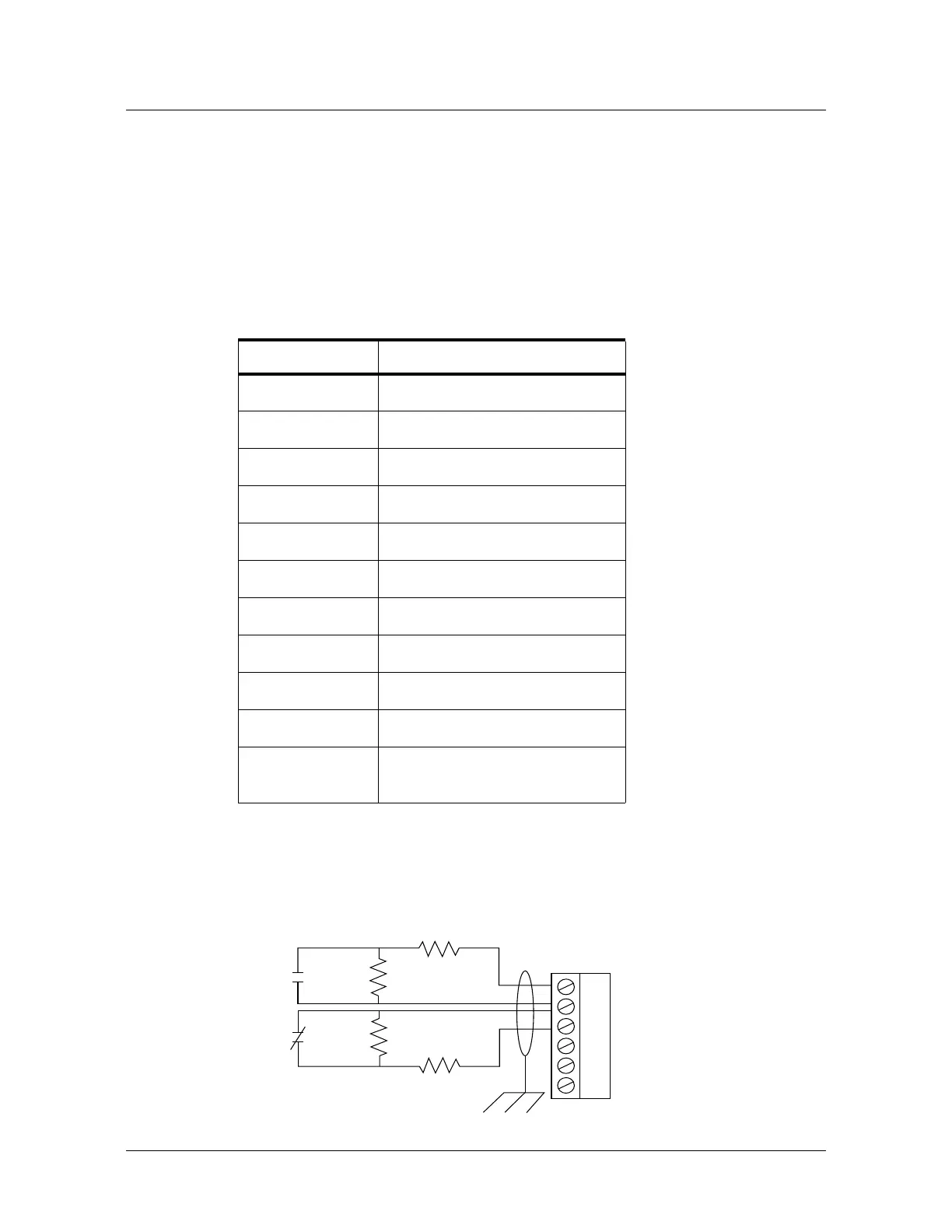
The following figure shows the typical wiring for a supervised input.
Figure 8: Typical Supervised Input Wiring Diagram
Table 3 Default Supervised Input Assignments
Terminal Position Default Function
TB4-1 Door 1 REX (Egress)
TB4-3 Door 1 Status
TB4-4 Door 2 REX (Egress)
TB4-6 Door 2 Status
TB8-1 External Power Supply AC FAIL
TB8-3 Panel Tamper
TB13-1 Door 3 REX (Egress)
TB13-3 Door 3 Status
TB13-4 Door 4 REX (Egress)
TB13-6 Door 4 Status
TB 5-6, 6-6, 11-6,
12-6
Optional supervised input if not used
for a reader tamper
NO
TB
NC
2.2K
2.2K
2.2K
2.2K
1
2
3
4
5
6
DOOR 1 EGRESS
COMMON
DOOR 1 STATUS
DOOR 2 EGRESS
COMMON
DOOR 2 STATUS

 Loading...


