EasyManua.ls Logo

Honeywell NOTIFIER LDM-32 - User Manual

Honeywell NOTIFIER LDM-32
68 pages
To Next Page IconTo Next Page
Loading...
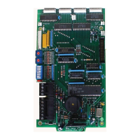
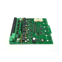
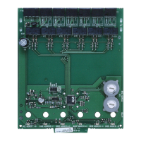
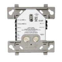
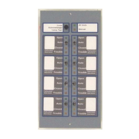
Lamp Driver Module
LDM Series
Instruction Manual
Document 15885 Rev: H3
8/12/2019 ECN: 18-0305

Table of Contents

Question and Answer IconNeed help?

Do you have a question about the Honeywell NOTIFIER LDM-32 and is the answer not in the manual?

Honeywell NOTIFIER LDM-32 Specifications

General IconGeneral
ModelLDM-32
Input Voltage24 VDC
Humidity Range10% to 93% non-condensing
Communication ProtocolNOTIFIER Protocol
Operating Temperature0°C to 49°C (32°F to 120°F)
CompatibilityCompatible with NOTIFIER fire alarm control panels
LED IndicatorsLoop status, fault, power

Summary

Installation Precautions

Power Disconnection and Safety Procedures

Details warnings about disconnecting power and general safety during installation.

System Re-acceptance Testing

Covers the requirement for system re-testing after software or component changes.

LDM Features

Cabinet and Chassis Mounting

Installation Checklist

Step-by-step guide for mounting the LDM modules in cabinets or chassis.

Wiring Considerations

EIA-485 Wiring Specifications

Outlines requirements for EIA-485 circuit wiring, distance, and impedance.

EIA-485 Shielding and Power Wiring

Covers EIA-485 shield termination and power/relay wiring details.

UL Power-Limited Wiring Requirements

Details UL requirements for separating power-limited and nonpower-limited circuits.

Lamp;LED Wiring

Control Switch Wiring

Operating the Lamp Driver Module

LAMP TEST;ACKNOWLEDGE Functionality

Explains the operation of the lamp test and acknowledge switch.

LDM Communications

Electrical Ratings and Current Calculations

Lamp Driver Electrical Ratings

Provides electrical specifications for LED power and driver outputs.

Calculating Standby and Alarm Currents

Guides on calculating system standby and alarm current draw.

Appendix A: System 500 (UL 8 th)

Configuration and Annunciator Operation

Explains LDM-32/System 500 configuration and annunciator point operation.

Appendix B: System 5000 (UL 8 th)

Appendix C: NFS2-3030;NCA-2;AM2020;AFP1010;NFS-3030;NCA

Configuration and Wiring for NFS;AM2020;AFP1010

Provides detailed setup and wiring for specific FACP models.

Appendix D: AFP-100 (UL 8 th)

Configuration for the LDM-32 and AFP-100

Explains DIP switch settings for LDM-32 with AFP-100.

Appendix E: AFP-200 (UL 8 th)

Appendix F: NFS2-640;NFS-320;AFP-300;400;NFS-640

Appendix G: SFP-1024 (UL 8 th)

Related product manuals