18 LDM Series Instruction Manual — P/N 15885:H3 8/12/2019
Wiring Considerations Supervision Input - TB1, Terminals 6 & 7
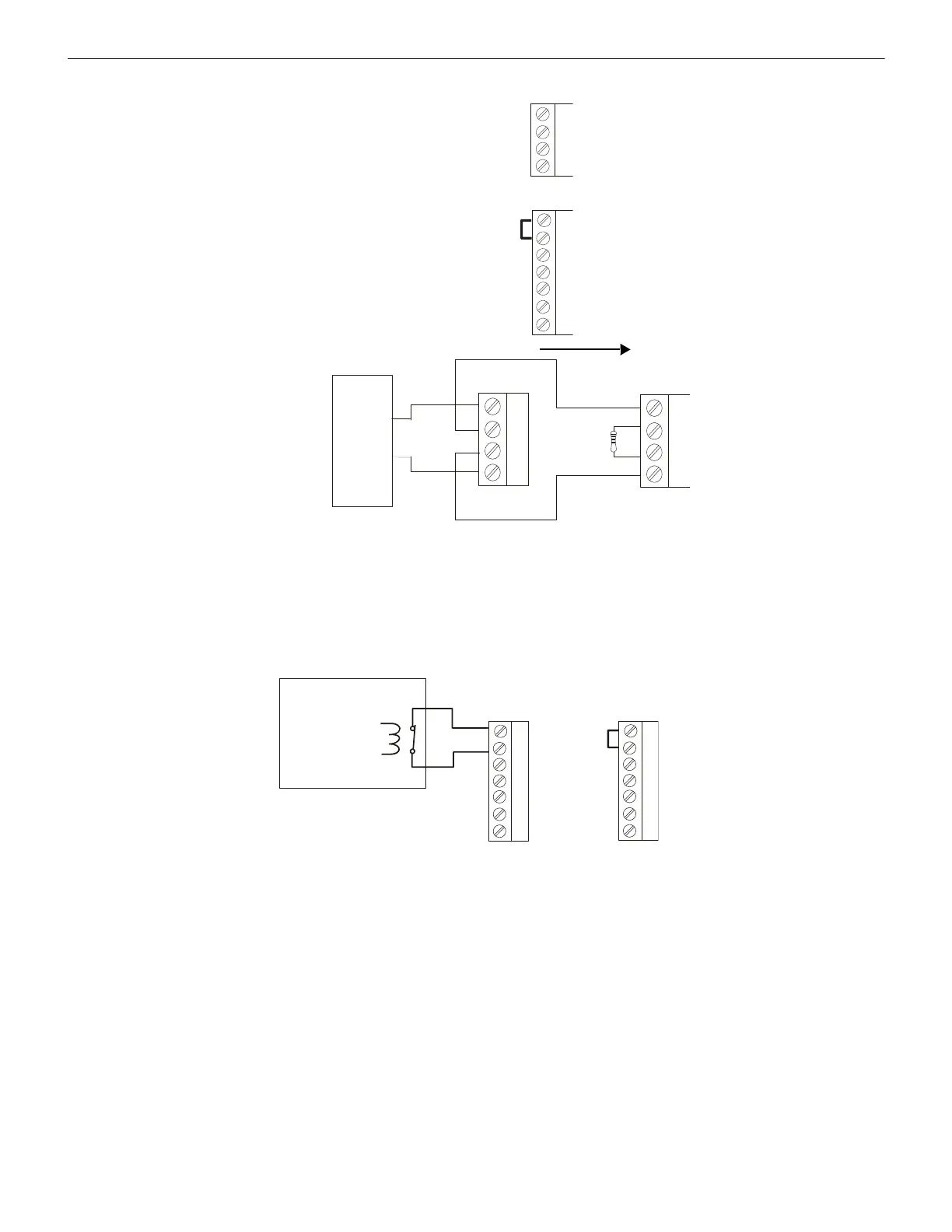
4.7 Supervision Input - TB1, Terminals 6 & 7
The Supervision Input, which requires a normally-closed condition, can be used for supervising power sources or other devices. It must
be power-limited. If employed, a change in status will be transmitted to the host control panel in the event of device failure or restoral. If
not used, a jumper must be installed across these terminals on TB1. A trouble signal will be registered by the control panel if a short cir-
cuit does not exist across terminals 6 & 7.
4.8 UL Power-Limited Wiring Requirements
Power-limited and nonpower-limited circuit wiring must remain separated in the cabinet. All power-limited circuit wiring must remain at
least 0.25" away from any nonpower-limited circuit wiring. Furthermore, all power-limited circuit wiring and nonpower-limited circuit
wiring must enter and exit the cabinet through different knockouts and/or conduits. A typical wiring diagram for the LDM-R32 is shown
+
+
+
+
-
-
-
-
TB2
TB2
EIA-485 (-)
EIA-485 (+)
EIA-485 IN (-)
EIA-485 OUT (-)
EIA-485 OUT (+)
EIA-485 IN (+)
N.C. Supervision
Inputs
Common In (-)
Common Out (-)
Power In (24 VDC)
Power Out (24 VDC)
Earth Ground
120W ELR
Part #71244
Host FACP
First LDM
Last LDM
Figure 4.5 Wiring Multiple LDMs - 6,000 ft. (1,800 m) max run
Device to be Supervised
Normally Closed
Trouble Contacts
Supervision
Input
Supervision
Input
5VDC @
0.5mA
When not using the Supervision input,
jumper terminals 6 & 7 together.
Figure 4.6 Wiring Supervision Terminals
 Loading...


