32 LDM Series Instruction Manual — P/N 15885:H3 8/12/2019
System 5000 (UL 8th) MPS-24A Main Power Supply
B.3 MPS-24A Main Power Supply
Connect the power run for the LDMs to MPS-24A TB3, Terminals 1 (+) and 2 (-). Maximum current is 1 amp. The power run to the
LDMs need not contain a Power Supervision Relay since loss of power is inherently supervised.
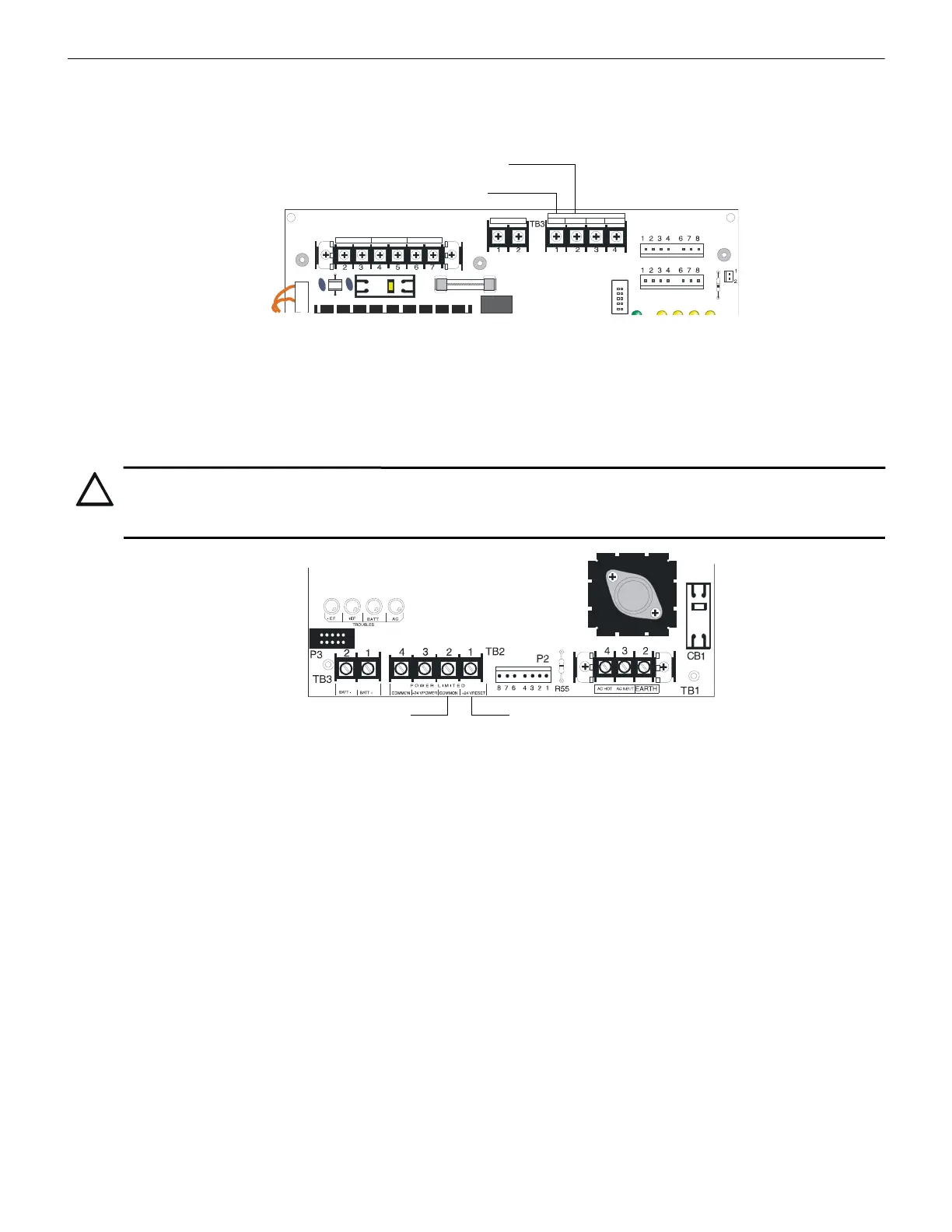
B.4 MPS-24B Main Power Supply
Connect the power run for the LDMs to MPS-24B, TB2, Terminals 1 (+) and 2 (-). No more than 200 mA current can be drawn from
these terminals in standby or alarm.
P2
EARTH GND AC NEUTRAL AC HOT
+24R COMMON +24
COMMON
POWER LIMITED
BAT + BAT -
MPS-24A
Common (-) TB3-2
24 VDC Power (+) TB3-1
Figure B.2 Connecting Power from the MPS-24A
CAUTION: POWER-LIMITED WIRING
THE +24 VDC PROVIDED ON TB2 TERMINAL 3 IS POWER-LIMITED ONLY WHEN USED WITH THE MINUS RETURN
ON TB2 TERMINAL 4. DO NOT USE THE MINUS RETURN ON TB2 TERMINAL 2 WITH THE +24 VDC POWER ON TB2
TERMINAL 3.
MPS-24B
24 VDC Power (+) TB2-1
(-) Common TB2-2
Figure B.3 Connecting Power from the MPS-24B
 Loading...


