LDM Series Instruction Manual — P/N 15885:H3 8/12/2019 47
Configuration for the LDM-32 and NFS-3030/NFS2-3030, NCA/NCA-2, or AM2020/AFP1010 NFS2-3030 and NCA-2 (UL 9th),
C.9 Configuration for the LDM-32 and NFS-3030/NFS2-3030, NCA/NCA-2, or
AM2020/AFP1010
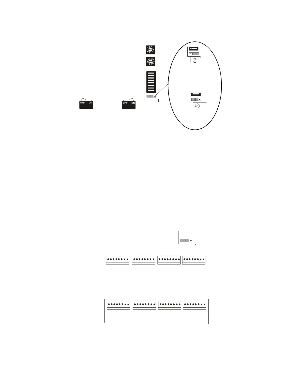
LDM-32 DIP Switch (SW3) settings
(for NFS-3030/NFS2-3030, NCA/NCA-2, or AM2020/AFP1010):
1. Relay Control: Set to ON when the lamp driver is used to control relays or to provide fan shutdown (see the Annunciator Control
System manual, Document 15842 for more details).
None One Two Three
2. Number of LDM-E32 Expanders Installed: OFF ON OFF ON
3. Number of LDM-E32 Expanders Installed:OFFOFFONON
4. 8-Point Shift: This switch must always be set OFF on the NFS-3030/NFS2-3030, NCA/NCA-2, or AM2020/AFP1010.
5. Receive Only: Set this switch ON for each LDM series that will provide the same information as another LDM series in a different
physical location (when two or more sets of LDM series have the same address, all but one must be configured as Receive Only.)
6. Piezo Disable: Set this switch ON to disable the piezo from sounding for any event.
7. Switch Inhibit: Set this switch OFF to enable any control switches wired to the Lamp Driver. If set ON, switches wired to the
Lamp Driver will not execute their intended functions, but will serve only as a local Lamp Test for their respective points.
8. Flash Inhibit: Set this switch ON to disable the flashing of LEDs associated with unacknowledged events. Flash Inhibit also
disables the piezo from sounding. Flash Inhibit must be ON when using the relay expander module (LDM-R32).
C.10 Wiring the LDM for the NFS-3030/NFS2-3030, NCA/NCA-2, or AM2020/AFP1010
The LDM-32 and one expander can be configured for up to 64 alarm points by setting Switch SW4 to the 'ALARM ONLY' position.
Figure C.2 Lamp Driver Alarm Points
LDM-32
Switch set to
ON position
Switch set to
OFF position
Lamp Driver Address
Set in the range 01-32
Ones
Tens
DIP Switch SW3
(see settings below)
SW4
SW4
ALARM/TROUBLE mode
(SW4 set to right side)
ALARM ONLY mode
(SW4 set to left side)
SW4
Points
P(1) - P(8)
LDM-32 Lamp Driver
Points
P(9) - P(16)
Points
P(17) - P(24)
Points
P(25) - P(32)
Points
P(33) - P(40)
Points
P(41) - P(48)
Points
P(49) - P(56)
Points
P(57) - P(64)
LDM-E32 Expander
 Loading...


