LDM Series Instruction Manual — P/N 15885:H3 8/12/2019 51
Configuration for the LDM-32 and AFP-100 AFP-100 (UL 8th)
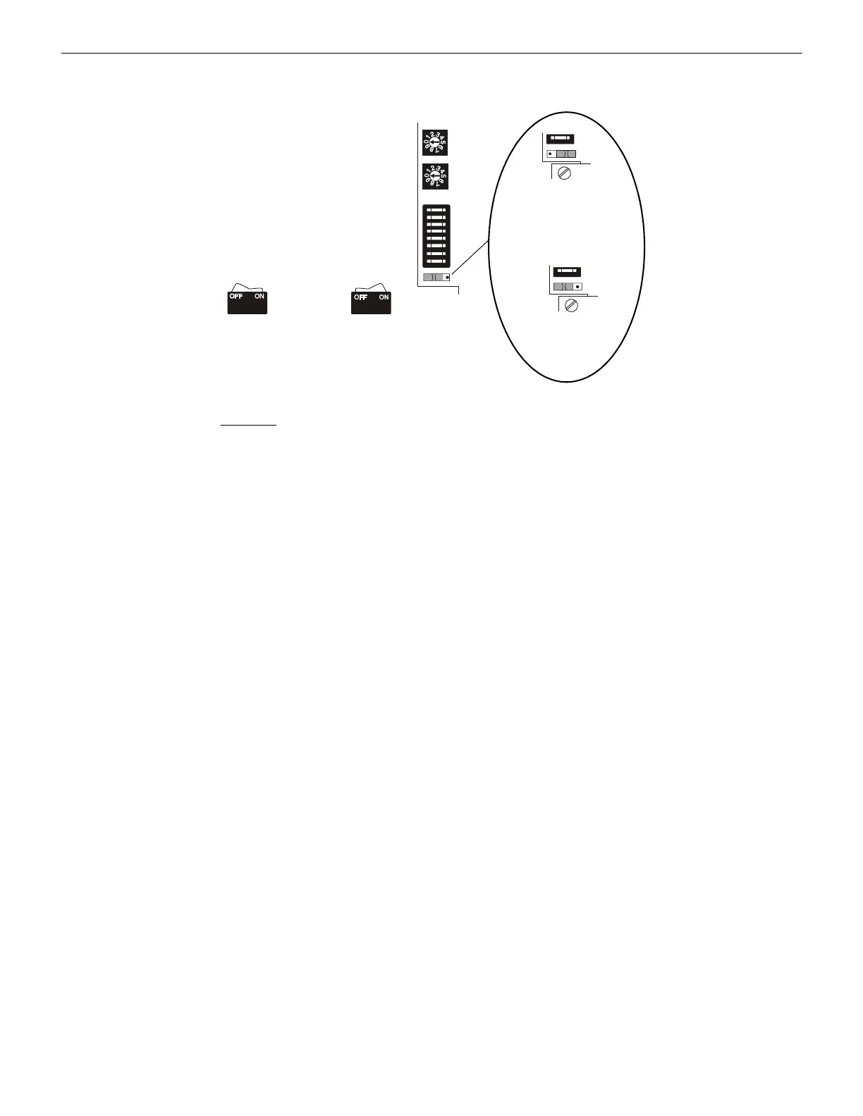
D.5 Configuration for the LDM-32 and AFP-100
LDM-32 DIP Switch (SW3) settings (for AFP-100):
1. Relay Control: Future Use - this switch must be set OFF on the AFP-100.
None One Two Three
2. Number of LDM-E32 Expanders Installed: OFF ON OFF ON
3. Number of LDM-E32 Expanders Installed: OFF OFF ON ON
4. 8-Point Shift: Set switch ON to shift MS-9200 LED function annunciation from the first eight annunciator positions on the
LDM-32F to the third LDM-E32F expander positions 57 - 64. This shift can only be set on an LDM-32F set for address 1 (system
using less than 56 software zones).
5. Receive Only: Set this switch ON for each LDM series that will provide the same information as another LDM series in a different
physical location (when two or more sets of LDM series have the same address, all but one must be configured as Receive Only.)
6. Piezo Disable: Set this switch ON to disable the piezo from sounding for any event.
7. Switch Inhibit: To disable the point I/O control switches on the LDMs from functioning, set this switch ON. When inhibited, the
local Lamp Test switch continues to function. In addition, the Acknowledge/Lamp Test switch will function only in a local
capacity, unrecognized by the host AFP-100.
8. Flash Inhibit: Set this switch ON to disable the flashing of LEDs associated with unacknowledged events. Flash Inhibit also
disables the piezo from sounding.
*The lamp driver must be set for addresses 1, 2, 3 or 4 when used with the AFP-100. Use address 1 for 56 zones. Use addresses 1, 2, 3
and 4 for 198 points. (Do not omit any address when annunciating 198 points or the AFP-100 will indicate a constant trouble). Refer to
Document 51010 for details.
LDM-32
Switch set to
ON position
Switch set to
OFF position
Lamp Driver Address
Set in the range 01-04
Ones
Tens
DIP Switch SW3
(see settings below)
Lamp Driver Mode
SW4
SW4
ALARM/TROUBLE mode
(SW4 set to right side)
ALARM ONLY mode
(SW4 set to left side)
 Loading...


