42 www.honeywell.com
NetAXS™ NX4L1 Installation Guide
System Configuration
5.0 System Configuration
This section provides wiring diagrams for each of the NetAXS system configurations.
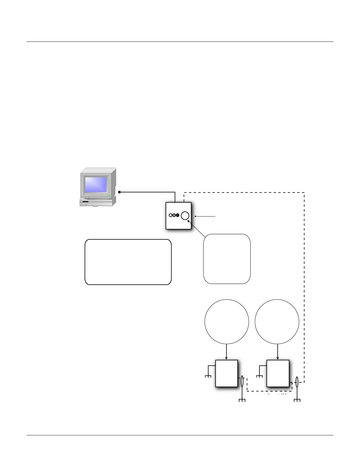
5.1 RS-485 Connection via PCI-2
This connection supports thirty-one NetAXS Access Controller panels for each drop line. Note that
PCI-2 units can also be wired in interior, as well as in endpoint, positions. See Figure 20 on page 44
and Figure 21 on page 45. Because UL has approved the NetAXS panel only as a standalone system,
the computer terminal, NetAXS gateway panel, and N-485_PCI-2 adapter appear in these sections
only to illustrate the installation and programming of the NetAXS panel.
Figure 18: RS-485 Connection via PCI-2
COM Port
It is recommended to Earth Ground (EG) each
NetAXS enclosure individually
RS-485 Cable
RS485 NetAXS Panels
Red/White
Black/Green
RS-485 COM
TB7-1 (RS485+)
TB7-2 (RS485-)
TB7-3 (RS485 COM)
4,000 ft. (1,200 m) max, 24 AWG, 2 twisted pairs with
shield, 120 ohm, 23 pf (HAS part no. NCP2441-TN)
Refer to N-485-PCI/NS2/NS2+
Access Controller Panel
Connection Detail diagram
DIP Switch Settings
S1: ON
S2: ON
S3: ON
S4: ON
S5: ON
S6: ON (Ack/Nak Enable)
S7: ON
S8: OFF (19,200 Baud
Rate)
See
RS-485
Cable
NetAXS
Panel
EG
EG
DIP Switch Settings
S1-S5 Panel Address
S6: OFF
J36 CLOSED
J37 CLOSED
EG
Only Earth Ground (EG)
one side of cable
RS-485 (4,000 ft.)
RS-232 (50 ft. max.)
N-485-PCI-
NetAXS
Panel
EG
DIP Switch Settings
S1-S5 Panel Address
S6: OFF
J36 OPEN
J37 OPEN
Terminal

 Loading...


