50 LDM Series Instruction Manual — P/N 15885:H3 8/12/2019
Appendix D: AFP-100 (UL 8th)
D.1 Capabilities
When installed with an AFP-100, LDM Series modules can annunciate the status of 56 software zones or 198 points plus system status.
Each lamp driver output is assigned to one and only one system I/O point:
• Addressable Devices:
– Addressable Detectors - SDX751, CPX751, FDX-551
– Monitor Modules - MMX-1, MMX-2, MX-101
– Control Modules - CMX
– Addressable Manual Pull Stations - BG-10LX
• System Control Switches:
– Acknowledge
– Signal Silence
– System Reset
–Drill
• Trouble Indication:
Communication between the AFP-100 and the LDMs is accomplished over a two-wire EIA-485 serial communication bus. The
EIA-485 is supervised by the AFP-100. Loss of communication results in System Trouble and Annunciator 1 (2) No Answer
message on the panel's 40 character LCD display.
D.2 Lamp/LED Driver Operation
Lamp Driver outputs do not latch - they track or follow the status of each zone/point they are assigned to annunciate. Table D.1 defines
the ON status of each lamp driver output.
D.3 Programming for Remote Annunciation
After complete installation, the LDM must be programmed into the AFP-100 before it will function. Program the LDM as if it were an
annunciator. Refer to the AFP-100 Technical Manual, Document 51010.
D.4 Installation Requirements
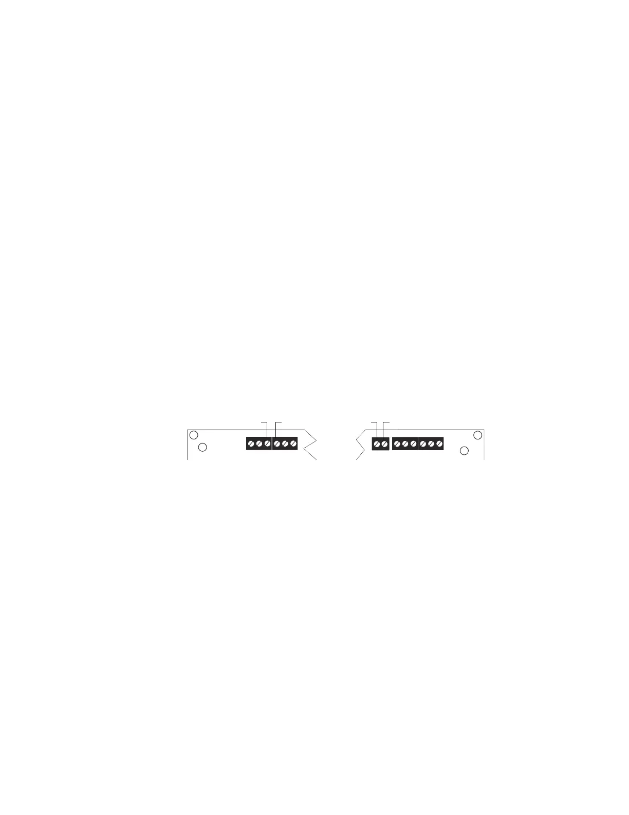
Regulated power (24 VDC) and the EIA-485 circuit that communicates with the LDMs must be connected to the AFP-100 as illustrated
below. Note that an external power source may be used to power the LDM Series.
For more information on annunciator operation and FACP programming under various specific applications, refer to the AFP-100 docu-
ments referenced in Section 1.3, “Related Documentation”, on page 7.
A B B+ A+ B- A-
1 COMM 2
ACS
SHIELD
SLC SLC
T
B
5
T
B
6
24V UNREG
24V NONRS 24V RST
+ - + - + -
T
B
4
24 VDC Power EIA-485 Circuit
TB4-3 (+)
TB5-1(+)
TB4-4 (–)
TB5-2 (–)
Figure D.1 AFP-100 Main Circuit Board (Top edge)

 Loading...


