24 LDM Series Instruction Manual — P/N 15885:H3 8/12/2019
Appendix A: System 500 (UL 8th)
A.1 Capabilities
When installed with a System 500, the LDM Series modules can annunciate the status of initiating and notification circuits, relays, and
several system control functions. Each lamp driver output is automatically assigned to one and only one system I/O point:
• Optional System 500 plug in Modules
– IZ-4/IZ-4A/IZ-8 - Initiating Device Circuits (alarm and trouble)
– IC-4/ICE-4/ICR-4L - Notification Appliance Circuits (activation and trouble)
– CR-4/CRE-4/CR-4L - Control Relay Modules (activation and trouble)
– TC-2/TC-4 - Time Control Modules (activation and trouble)
• System Control Switches
– Acknowledge
– Signal Silence
– System Reset
– Activate Notification Circuits 1 and 2, the Remote Signaling
– Municipal Tie circuit and the Alarm Relay
A.2 System 500 Trouble Indication
Communication between the CPU and the LDMs is accomplished over a two-wire EIA-485 serial communication bus. The EIA-485 bus
is supervised by the System 500. Loss of communication results in System Trouble and Module Failure indications at the CPU.
A.3 Installation Requirements
The EIA-485 circuit that communicates with the LDM must be connected to the CPU as illustrated in Figure A.1. The LDM-32 also
requires filtered, regulated power. Refer to Figure A.2 for power supply connections.
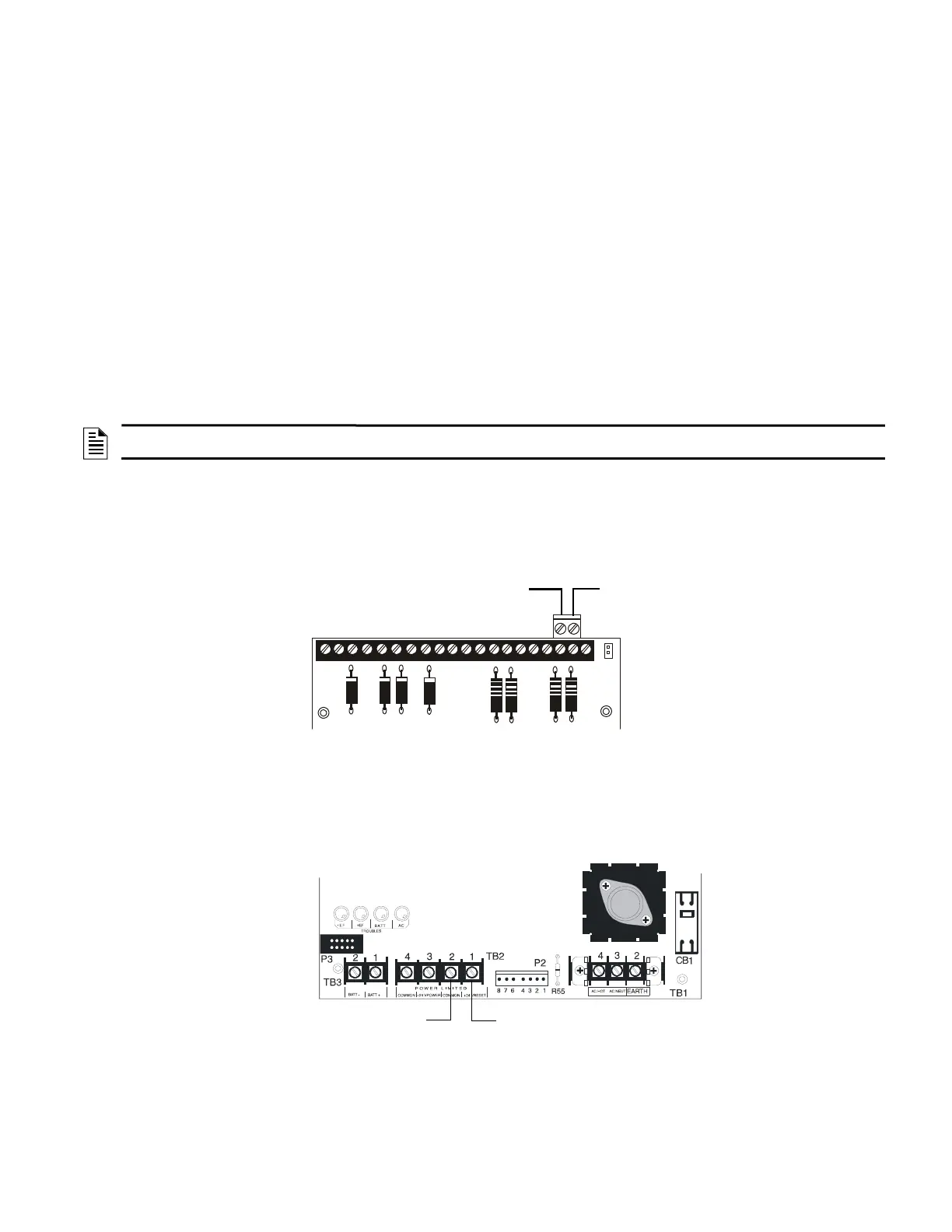
A.4 MPS-24BPCC Main Power Supply (System 500 Only)
Connect the power run for the LDM-32 to MPS-24BPCC TB2 terminals 1 (+) and 2 (-) (power-limited). No more than 200 mA current
can be drawn from these terminals in standby or alarm.
For more information on annunciator operation and FACP programming under various specific applications, refer to the System 500
documents referenced in Section 1.3, “Related Documentation”, on page 7.
NOTE: 'System Trouble' and 'Module Failure' will also occur if the normally closed supervisory path between TB1 Terminals 6 and 7 on the
annunciator is opened (or the jumper has not been installed).
Supervised and Power-Limited
(+) EIA-485
to LDM TB2 Terminal #1
EIA-485 (-)
to LDM TB2 Terminal #4
CPU-500
Figure A.1 Connecting the EIA-485 Loop to the CPU-500
24 VDC Power (+) TB2-1
(-) Common TB2-2
MPS-24BPCC
Figure A.2 Connecting Power from the MPS-24BPCC

 Loading...


