LDM Series Instruction Manual — P/N 15885:H3 8/12/2019 9
The LDM-32 LDM Features
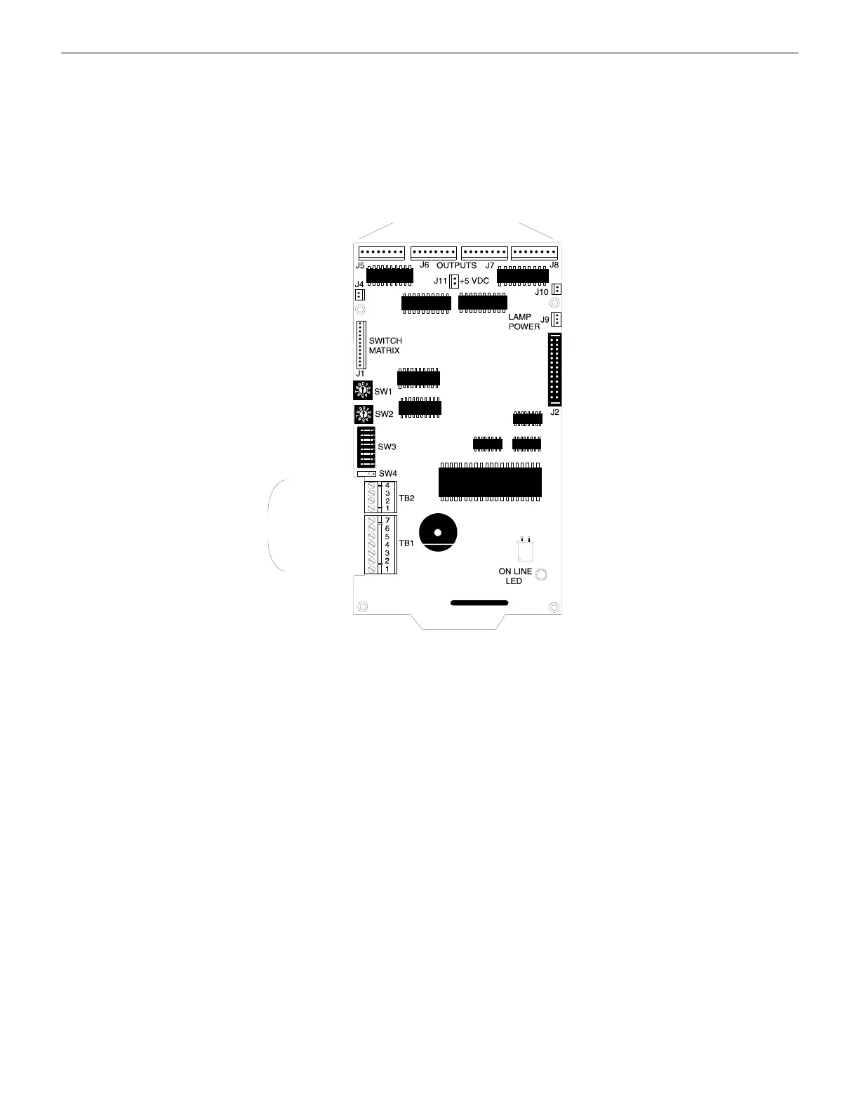
2.2 The LDM-32
The Lamp Driver Module LDM-32 has 32 alarm lamp/LED driver outputs which sink current to system common (-) on activation. A sin-
gle positive (+) voltage is required to supply total operating power for all lamps or LEDs when all drivers are activated. The LDM-32
provides a separate driver for system trouble and inputs for a local lamp test switch. A maximum of 16 external control switches may be
wired to the LDM-32. DIP switch SW3 is used to enable or disable the onboard piezo, enable remote switch functions, select a flashing
LED function for new alarms and troubles, and other functions. Switch SW4 is used to configure the module to annunciate 32 alarms or
16 troubles. A green ON LINE LED flickers to indicate ongoing communications with the host FACP. One LDM-32 supports up to 3
LDM-E32 modules. The LDM-32 is supplied with 4 standoffs and screws for mounting to a chassis or custom backbox.
Output Connectors for
Wiring to LEDs
Security Key
Switch Terminal
Terminal for max.
of 16 external
control switches
Address Switches
LDM Program Switch
Alarm or Alarm/Trouble
EIA-485 In (-)
EIA-485 Out (-)
EIA-485 Out (+)
EIA-485 In (+)
Supervision
Inputs (NC)
Common In (-)
Common Out (-)
Power In +24 VDC
Power Out +24 VDC
Earth Ground
Power-
limited
Flickers to
indicate EIA-485
Communication
Active
Ribbon Cable
Connection to
LDM-E32
System Trouble
Lamp Power (+24 VDC)
Relay Power Ribbon
Cable Connection
Figure 2.1 LDM-32

 Loading...


