LDM Series Instruction Manual — P/N 15885:H3 8/12/2019 19
Lamp/LED Wiring Wiring Considerations
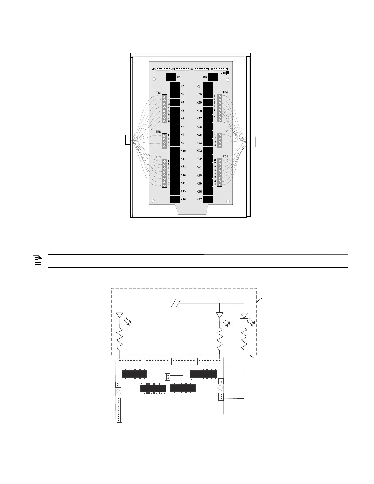
below. If this module is used to drive both power-limited and nonpower-limited circuits, connect relays 1 to 16 to power-limited circuits
and connect relays 17 to 32 to nonpower-limited circuits or vice versa. Use an appropriate power-limited power supply which is UL
listed for fire alarm systems to provide power for the power-limited circuits.
4.9 Lamp/LED Wiring
• Figure 4.8 illustrates LEDs being powered by the 5V output from LDM-32, J11 pin 1.
• Figure 4.9 illustrates LEDs being powered by the 24V output from LDM-32, J9 pin 3.
Power-
Limited
Circuits
Nonpower-
Limited
Circuits
LDM-R32
Figure 4.7 Wiring Requirements
NOTE: All LEDs/lamps being driven by the LDM series must be located in the same room as the modules. Use cable kits for wiring from
connectors on LDM.
J11
+5
Common
J6
J5
J4
SWITCH
MATRI X
LAMP
POWER
OUTPUTS
J7
J8
J10
J9
Point Status LEDs:
Use red for alarm points,
yellow for trouble points, and
green for output points
Use 680 W, 1/4 watt resistors for
each point if using 2 mA LEDs.
Custom
Graphic
Display
Wiring is
not
supervised
System
Trouble LED
(Yellow)
Note: All LEDs must be in the same room as the LDM modules.
Figure 4.8 Typical LDM-to-Graphics Display Connection @ 5VDC

 Loading...


