12 FDU-80 Instruction Manual — P/N 51264:C2 4/24/2019
Section 4: Mounting
4.1 Annunciator Preparation
The FDU-80 Annunciator can be surface mounted in a three-gang electrical box such as the P/N SBB-3 (2.75" depth) or semi-flush
mounted in a three-gang electrical box, P/N 10103 or equivalent, with a minimum depth of 2.1875". The FDU-80 Annunciator can also
be mounted in three gangable electrical switch boxes connected together. Select and remove the appropriate knockout(s), pull the neces-
sary wires through the knockouts and mount the box in or on the wall depending on the type of installation desired. Be certain that power
is not applied to the wiring during the installation procedure.
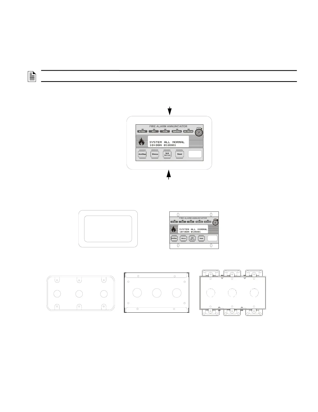
To mount the FDU-80 Annunciator in an electrical box, the trim ring must first be removed. The trim ring is held in place by two screws
inserted through the top and bottom edge as illustrated in Figure 3-1. Removal of the trim ring will expose a metal flange with mounting
holes. Refer to “Hardware and Backboxes” on page 12.
4.2 Semi-flush Mount Backbox
NOTE: To ensure static protection, all enclosures, including the FDU-80 electrical box, must be connected to earth ground! Never use the
shield for grounding purposes.
Screw
Screw
LCD-80F.cdr
Figure 4.1 Trim Ring Removal
FDU-80 flange
FDU-80 Trim Ring
(replacement P/N 23165)
3-Gang Electrical Box P/N 10103
(semi-flush mount)
3-Gang Electrical Box P/N SBB-3
(surface mount)
Three Ganged Electrical Boxes
Figure 4.2 Hardware and Backboxes

 Loading...