8 FDU-80 Instruction Manual — P/N 51264:C2 4/24/2019
The FDU-80 Annunciator Components
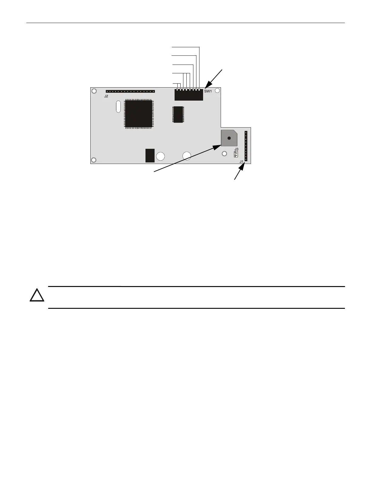
2.3 Components
2.4 SW1 DIP Switch Settings
Refer to “DIP Switch Settings Example” on page 9, for an explanation of DIP switch positions. SW1 switch settings follow:
1 -ON = Key-switch disabled, OFF = Key-switch enabled.
Switch 1 set to the OFF position enables key-switch operation. The key-switch may now be used to enable the FDU-80
membrane switches, allowing remote switch functions, or lockout the switches, preventing remote switch functions.
Switch 1 set to the ON position disables the key-switch operation. Refer to “Switch Functions” on page 10, for key-switch function
description.
2 -ON = Piezo sounder enabled, OFF = Piezo sounder disabled.
3 -ON = Supervision Receive/Transmit, OFF = Supervision Receive Only.
• One Annunciator - if a single FDU-80 is the only annunciator connected to the EIA-485 loop, Switch 3 must be set to the ON
position to allow the FACP to supervise the annunciator.
• Multiple Annunciators - if multiple FDU-80 annunciators are connected to the EIA-485 loop, the annunciator physically
connected as the last device on the loop (farthest from the ‘OUT’ terminals on the FACP) must have Switch 3 set to the ON position
in order to supervise all annunciators on the loop. All remaining annunciators must have Switch 3 set to the OFF position for
proper supervision and operation.
It is important to note that the function switches on all FDU-80 annunciators will operate regardless of the setting of Switch 3.
A break (open circuit) in the power or EIA-485 connections creates an FDU-80 Annunciator fault at the control panel. All annunciators
before the break will continue to display information (but the function switches on these FDU-80s will no longer operate).
4 through 6 = Configuration for use with a particular FACP.
Switches 4, 5 and 6 are used to select the FACP (Fire Alarm Control Panel) which is being connected to the FDU-80. Refer to the follow-
ing table for the appropriate switch settings.
Future use
ON = Piezo Enable
OFF = Key-switch Enabled
OFF = Receive only
Top view
Note: See “DIP Switch Settings
Example” on page 9.
The FDU-80 sounder, if enabled, will be activated when any new
alarm or trouble is received from the panel. It is silenced by an
Acknowledge switch. Piezo must not be disabled without approval
of the Local AHJ (Authority Having Jurisdiction).
Piezo Sounder
Membrane Connector
Cable connection to membrane switches for
Acknowledge, Silence, Drill and Reset.
Panel Configuration
Figure 2.1 Components of the FDU-80
CAUTION: AHJ APPROVAL
THE PIEZO SOUNDER MUST NOT BE DISABLED WITHOUT PRIOR APPROVAL OF THE LOCAL AUTHORITY HAVING
JURISDICTION (AHJ).

 Loading...