14 FDU-80 Instruction Manual — P/N 51264:C2 4/24/2019
Mounting Surface Mount Backbox
4.3 Surface Mount Backbox
Remove the plug-in terminal blocks from the FDU-80 circuit board. Connect the EIA-485 and power wiring into the terminal block posi-
tions illustrated in Figure 5.1 on page 15 through Figure 5.5 on page 16. Plug the terminal blocks back into the P2 and P1 connectors on
the back of the annunciator circuit board. Set DIP switch SW1 for the desired options. Refer to Figure 2.2 on page 9.
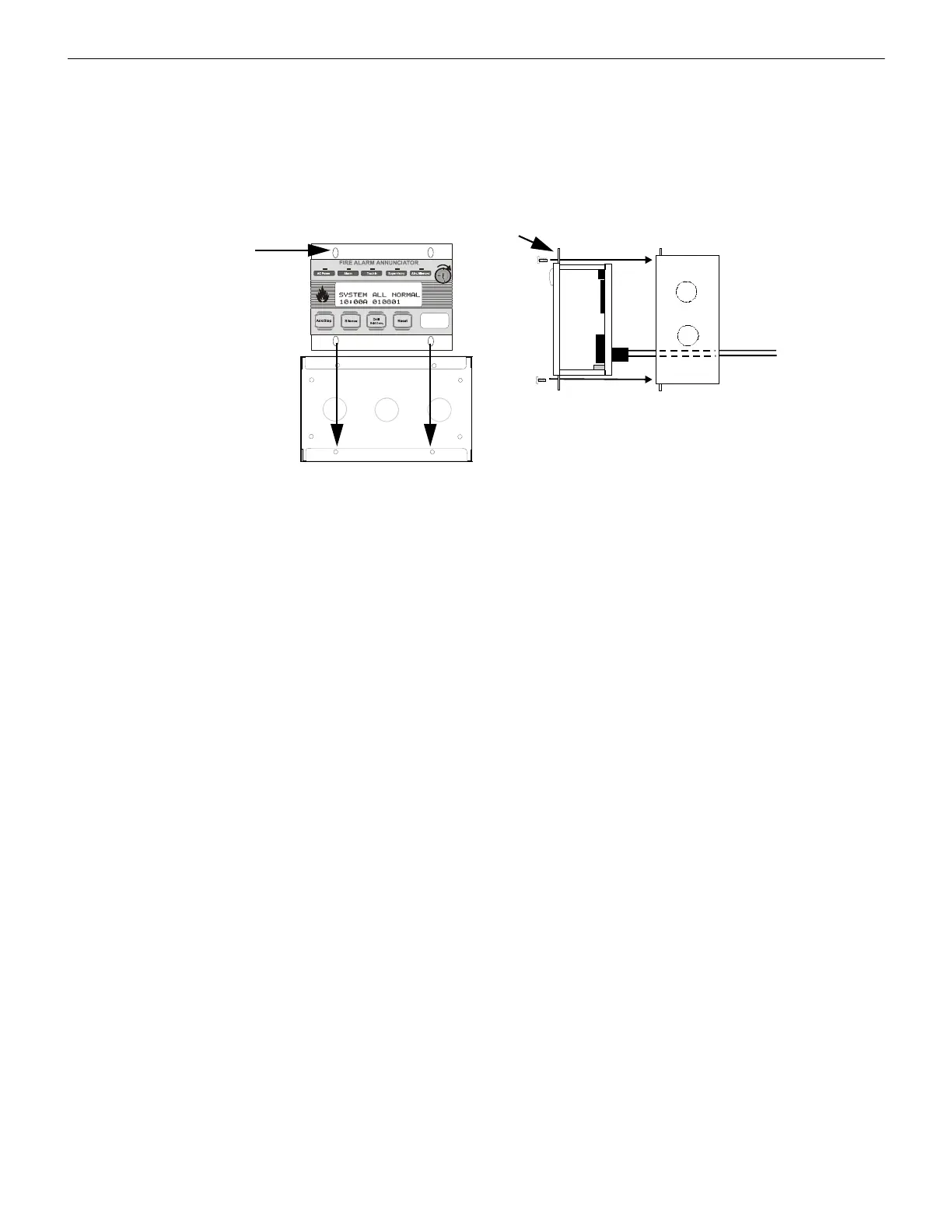
Carefully insert the FDU-80 into the three-gang electrical box and attach it using the four mounting holes on the FDU-80 flange and the
four screws provided for this purpose. Replace the trim ring and secure with the two screws which were previously loosened. Do not
overtighten.
FDU-80 flange
Mounting holes (4)
The FDU-80 can be surface
mounted in a three-gang
electrical box, P/N SBB-3 or
equivalent, with a minimum
depth of 2.75".
FDU-80
Three-gang surface box P/N SBB-3
flange
EIA-485 and power wiring
Figure 4.5 Surface Mounting

 Loading...