5
Installing the Kit PSU7A Assembly in a Remote Enclosure (Continued)
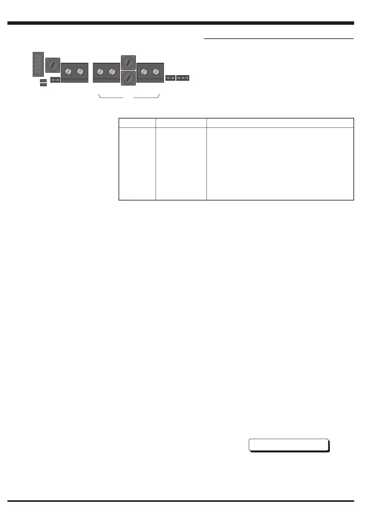
Connector Cable Size Instruction
22
(i) 0.5mm -2.5mm Charger Inhibit.
(ii) Not applicable Optional Status Indication kit, PN: 020-548, can be connected here.
2
(iii) <1.4m - use 1.5mm Dual Transmission Path supply cables. The cables listed
2
<2.3m - use 2.5mm here are example sizes for various distances (termination to
2
<3.8m - use 4mm termination) between the panel and the power supply unit.
2
<6.0m - use 6mm Lengths are for systems drawing the max of 7A (typically Alarm
2
<10.0m - use 10mm current). Wire lengths may be increased proportionally for lower
All rated at 15A currents.
2
(iv) 84/0.3 (6mm ) Battery leads.
22
(v) 0.5mm -2.5mm Fault relay Common (pin 1) and Normally Open (pin 3).
Wiring Connections
When mounting the PSU7A in an external battery box, the
following supplied cables are not required:
a) The orange and green wires.
b) The red and black wires.
c) The ribbon cable with attached ferrite.
The following Table describes suitable cables for wiring the
remote PSU:
Connect the wiring to the PSU as follows:
1 Connect the PSU7A Charger Inhibit wiring between the ‘CI’
connector (i) and the DTP/Booster module in the panel,
using suitable cables as detailed in the table above. Connect
+ to + and - to -.
2 Connect the PSU output (iii) to the DTP/Booster module
using suitable cables, as detailed in the table above, to
provide the dual transmission path.
3 DO NOT CONNECT THE BATTERIES UNTIL
INSTRUCTED TO DO SO IN THE INSTALLATION AND
COMMISSIONING MANUAL. Use the appropriate cables
supplied in the Remote Enclosure kit to connect to the
battery connector (iv). Follow the connection procedure
given in the manual but note that any references to a
connector should be replaced by references to ring
terminals. Cut ring terminals off where required. When
instructed, connect to the battery. ENSURE CORRECT
POLARITY.
4 Connect the PSU7A fault relay wiring between the Common
Fault connector (v) and the DTP/Booster module in the
panel, using suitable cables as detailed in the table above.
Connect the C to COM and N/O to N/O.
5 Mount the thermistor on the batteries away from any heat
source.
Continued overleaf.....Continued overleaf.....
- -
+ +
I/OI/O
CI+ CI-CI+ CI-
COM N/C N/OCOM N/C N/O
TH- TH+TH- TH+
FAULT RELAYFAULT RELAY
(i)
(v)
(iii)
(iv)
(ii)
BATT + BATT -
997-277-000-9, Issue 9 February 2010

 Loading...