10
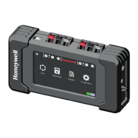
The POL200TS unit reports any short-
circuit fault conditions in the loop (showing
a lightning icon ), and reverse polarity
wiring (a diode icon ). It can also identify
within seconds the total number of devices
connected to the loop. This icons will appear
in the lower right corner.
Refer to the installation recommendations enclosed to the fire detection control panel to
connect the monitored loop to POL200TS. The fire panel installation manual includes the
different type of cables that should be used.
The following table shows the approximate resistive values for two recommended loop cable
types:
500mts 750mts 1000mts 1250mts 1500mts 2000mts 2500mts 3000mts
Cable 1.5mm
2
7 10 13 17 20 27 33 40
Cable 2.5mm
2
4 6 8 10 12 16 20 24
Shielded/screen cables should only be connected to ground, GND, on one point inside the fire
panel. The POL200TS allows the user to confirm that the shield is continuous, so it should be
approximately twice (2x) and three (3x) times the resistance of the negative conductor. So, in
case that the negative conductor has a:
• Capacitance between loop conductors + and – is below 0.5mF or 500nF
• Impedance between positive and cable shield (Infinite).
Confirm that the loop wiring is correct:
• The characteristics considered are for wiring in closed loop mode (from output and back to
input)
• The maximum resistance allowed from the OUTPUT end of the fire detection
panel (or from POL200TS) to the INPUT in the fire detection panel is 40 ohms.
 Loading...
