® U.S. Registered Trademark
Copyright © 1998 Honeywell Inc. • All Rights Reserved
INSTALLATION INSTRUCTIONS
66-1092-2
EC7830A, RM7830A, EC7850A, RM7850A
7800 SERIES Relay Modules
APPLICATION
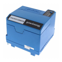
The Honeywell EC/RM7830A and EC/RM7850A are
microprocessor-based integrated burner controls for
automatically fired gas, oil, or combination fuel single burner
full modulation (EC/RM7850A) or on/off (EC/RM7830A)
applications. The EC/RM7830A; EC/RM7850A system
consists of a relay module, subbase, amplifier, and purge
card. Options include keyboard display module (KDM),
Personal Computer Interface, Data ControlBus Module™,
remote display mounting and Combustion System Manager®
Software.
Functions provided by the EC/RM7830A and EC/RM7850A
include automatic burner sequencing, flame supervision,
system status indication, system or self-diagnostics and
troubleshooting. Text readout on the Keyboard Display Module
is available in English, Spanish, Portuguese, Katakana
(Japanese), French, Chinese, German, and Italian languages.
This document provides installation and static checkout
instructions. Other applicable publications are:
63-2278: Q7700 Network Interface Unit Product Data.
65-0084: Q7800A,B 22-Terminal Wiring Subbase
Product Data.
65-0090: S7800A Keyboard Display Module Product Data.
65-0091: S7810A Data ControlBus Module™ Product
Data.
65-0228: S7810B Multi-Drop Switch Module Product Data.
65-0095: S7820 Remote Reset Module Product Data.
65-0097: 221729C Dust Cover Packing Instructions.
65-0102: ZM7850A Combustion System Manager®
Operating Instructions.
65-0109: R7824, R7847, R7848, R7849, R7861, R7886
Flame Amplifiers for the 7800 SERIES
Product Data.
65-0131: 221818A Extension Cable Assembly Product
Data.
65-0229: 7800 SERIES Relay Modules Checkout and
Troubleshooting Product Data.
SPECIFICATIONS
Electrical Ratings (See Tables 3A, 3B, 3C and 3D):
Voltage and Frequency:
RM7830A and RM7850A:
120 Vac (+10/-15%), 50/60 Hz (±10%).
EC7830A and EC7850A:
220/240 Vac (+10%/-15%), 50/60 Hz (±10%)
Power Dissipation: 10W maximum.
Maximum Total Connected Load: 2000 VA.
Fusing Total Connected Load: 20A maximum, type FRN or
equivalent.
Environmental Ratings:
Ambient Temperature:
Operating: -40°F to 140°F (-40°C to +60°C).
Storage: -40°F to 150°F (-40°C to +66°C).
Humidity: 85% relative humidity continuous,
noncondensing.
Vibration: 0.5G environment.
Approvals:
RM7830A and RM7850A:
Underwriters Laboratories Inc. Listed: File No. MP268,
Guide No. MCCZ.
Canadian Standards Association Certified: LR9S329-3.
Factory Mutual Approved: Report No. J.I.1V9A0.AF.
Industrial Risk Insurers: Acceptable.
Federal Communications Commission: Part 15,
Class B, Emissions.
EC7830A and EC7850A: Factory Mutual Approved.
These products also comply with the following European
directives:
Gas Appliance Directive: 90/396/EEC.
Low Voltage Directive: 73/23/EEC.
EMC Directive: 89/336/EEC.
GASTEC: CE-63AP3070/1.
Lloyds Register Approval.
Oil appliances:
EC7830A: DIN-5F 106/96.
EC7850A: DIN-5F 107/96.
These products are approved according to EN298, “Automatic
gas burner systems for gas burners and gas burning
appliances with or without fans.”
Please note the following to comply with EN60730 for remote
mounting of the KDM and/or remote reset module. It is
necessary to provide electrical separation using insulation at
least equivalent to double or reinforced insulation. This can be
accomplished by either:
1. Optically isolating the communication and/or remote
reset lines from the control cabinet or
2. Providing physical separation from the communication
and/or remote reset lines using electrical conduit and a
204718a Remote Display Cover Assembly or other
suitable enclosure that meets ip40 class of protection.





 Loading...