Do you have a question about the Honeywell EC7895A1010 and is the answer not in the manual?
Describes the RM7895/RM7896/EC7895 modules and their primary functions as microprocessor-based integrated burner controls.
Lists related documents for installation and checkout procedures, providing essential supporting information for the relay modules.
Details voltage, frequency, power dissipation, and load limits for the relay modules, crucial for proper system integration.
General safety warnings, important notes, and precautions for safe and correct installation of the relay module.
Specific instructions and recommendations for correctly mounting the wiring subbase for the relay module.
Guidance on choosing a suitable installation location considering environmental factors like humidity, vibration, and weather.
Explains how to match different series of relay modules with compatible subbase models for correct installation.
Steps to ensure correct wiring and power supply verification before the relay module is installed on the subbase.
Lists required tools and outlines the steps for performing static checkout tests to verify system functionality.
Directs users to applicable specifications for mounting other related system components alongside the relay module.
Details the specific events or conditions that cause the relay module to enter a safety shutdown or lockout state.
Explains the different stages of the burner control program: Initiate, Standby, Pre-Purge, PFEP, MFEP, and Run.
Describes how to use the Run/Test switch and site-configurable jumpers to adjust module behavior and safety levels.
Recommendations for protecting the device from unauthorized access, tampering, and environmental damage.
Guidelines for protecting communication interfaces from damage or tampering to ensure device functionality.
Legal restrictions regarding copying, reverse engineering, and proprietary rights of the product.
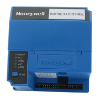
The Honeywell RM7895A,B,C,D/EC7895A,C; RM7896A,C,D 7800 Series Relay Modules are microprocessor-based integrated burner controls designed for automatically fired gas, oil, or combination fuel single burner applications. These modules are intended as replacements for the R4795 and R7795 Primary Controls. The systems comprise a relay module, subbase, amplifier, and purge card, with the RM7896 models additionally providing a postpurge function.
The core function of these relay modules is to provide automatic burner sequencing, flame supervision, system status indication, and system or self-diagnostics for troubleshooting. They manage the entire burner operation from initiation through shutdown.
The operating sequence begins with an INITIATE period when the relay module is powered or when voltage/frequency fluctuations are detected. This period ensures stable power conditions before proceeding. If conditions are not met, a hold condition is initiated, and prolonged issues lead to lockout. The INITIATE sequence also delays the burner motor starter to prevent erratic operation from intermittent AC line input.
Following INITIATE, the system enters the STANDBY period, awaiting a call for heat. Once a call for heat is present and all monitored circuits are in the correct state, the system transitions to the PREPURGE sequence. During PREPURGE, the burner motor output (terminal 4) is powered, and the Airflow Interlock input must close within a specified time. Failure to do so results in a recycle to PREPURGE or lockout, depending on the Airflow Switch jumper configuration.
After PREPURGE, the system proceeds to the IGNITION TRIALS, starting with the Pilot Flame Establishing Period (PFEP). During PFEP, the pilot valve and ignition transformer (terminals 8 and 10) are energized. Flame must be proven within the PFEP duration (ten seconds, or four seconds if Configuration Jumper JR1 is clipped) to continue the sequence. If flame is not proven, a safety shutdown occurs. Once flame is proven, the ignition (terminal 10) is de-energized. For specific models (RM7895C1020/2020 and RM7896C1036/2036), terminal 10 de-energizes within the first 8 seconds of PFEP if a flame signal is detected, and re-energizes if the signal is lost.
The Main Flame Establishing Period (MFEP) follows PFEP. With flame present, the main fuel valve (terminal 9) is powered. If a flameout occurs, the relay module locks out or recycles based on the JR2 jumper status and the Flame Failure Response Time (FFRT) of the amplifier. For EC7895C, RM7895C,D, and RM7896C,D models, MFEP lasts ten seconds, and the pilot valve (terminal 8) is de-energized after Ignition Trials.
Finally, the system enters the RUN period, where it remains until the controller input (terminal 6) opens, indicating that the demand is satisfied or a limit has opened. For EC7895C, RM7895C,D, and RM7896C,D, a delayed main valve is energized once RUN is entered.
For RM7896A,B,C,D models, a POST PURGE function is activated after demand is satisfied or a limit opens. During this period, the Ignition/Pilot valve, main valve, and delayed main valve (terminals 8, 9, and 21) are de-energized, while the blower motor (terminal 4) remains powered for 15 seconds.
Safety shutdowns (lockouts) can occur during various periods due to issues such as missing or bad purge cards, configuration jumper changes after 200 hours (Fault Code 110), AC line power errors, exceeding the INITIATE period, airflow switch failures, flame signal issues, internal system faults, or removal of the purge card.
The relay modules offer several features to enhance usability and system management: