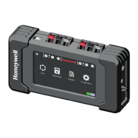
The Honeywell POL-200-TS is an analogue loop diagnostic tool designed for the preliminary check of loop device installations compatible with Notifier control units. This device features a color touch screen display and is compatible with both CLIP/ADVANCED protocols from Notifier, offering additional multimeter and oscilloscope functions.
Function Description:
The POL-200-TS simplifies initial wiring tests and allows for the export of data to PK-8200 software, which includes information on detected device types. Its user-friendly interface and one-touch functions enable operation even while wearing gloves. The mapping function, which uses loop isolators, helps verify the loop cabling topology. The screen can display manufacturing dates and detailed information about sensors, inputs, and outputs, as well as identify equipment status or internal faults.
The log function creates a file containing the status and data of each loop device, facilitating accurate system operation control by anticipating and recording maintenance tasks. These saved files can be easily downloaded via USB without special software, allowing for retrieval, review, checking, and configuration of the system. Both the device and the log file include the serial number and manufacture date (month/year) of each device. The multimeter validates wiring and identifies connection problems, while the oscilloscope function helps identify electrical noise.
The tool recognizes sensors and modules on the loop before powering the fire alarm control panel (FACP). It is compatible with CLIP (Classic Loop Interface Protocol) for up to 99 sensors and 99 modules, and the Advanced or Opal protocol for up to 159 sensors and 159 modules. The auto-programming menu identifies the number and type of connected sensors or modules. The reading cycle can be continuous or single-cycle, scanning all positions to find connected devices.
The POL-200-TS reports short-circuit fault conditions (indicated by a lightning icon) and reverse polarity wiring (indicated by a diode icon). It can also quickly identify the total number of devices connected to the loop. The multimeter function allows checking line impedance, resistance, inductance, and capacitance values, as well as ground values. It also displays voltages (0V, 5V, 24V) and consumption, helping to identify drifts, short circuits, faulty elements, or inadequate system devices.
The "Map" function visually checks the loop wiring map. If isolators are correctly wired, the POL-200-TS activates them and displays a graph. It provides a device map for CLIP or Advanced protocols, with device positions potentially changing based on the protocol. The "Sample" option allows users to select a list of devices for continuous monitoring with detailed information in CLIP mode for addresses below 99. The "Event Recording" function allows selected values from the self-programming screen to be recorded in a text file, with options for "Only selected items," "Full loop," and "Maintenance."
Important Technical Specifications:
- Power Supply: 12 V charger (included)
- Autonomy: >6 hours with 100% charged batteries (up to 6 hours depending on loop load)
- Batteries: 6x AA 1.2V NiMH 2500mAh, with quick charge in 1 hour
- Screen: 4.2" TFT 480 x 263 pixels (98x56mm) with 66,000 colors
- Keypad: Dynamic capacitive touchpad
- Dimensions: 97mm (h) x 177mm (w) x 44mm (d) (including rubber case)
- Colour: Black box with grey rubber protection
- Weight: 550g (including batteries)
- Operating Temperatures: 0°C to 50°C
- Charge Temperatures: 0°C to 40°C
- Storage Temperatures: -20°C to 30°C
- Humidity: 65 ± 20%
- Maximum Loop Resistance: 40 ohms from the OUTPUT end of the fire detection panel (or POL-200-TS) to the INPUT.
- Capacitance between loop conductors: Below 0.5mF or 500nF.
- Impedance between positive and cable shield: Infinite.
Usage Features:
- Connection: Spring-loaded connectors for loop cables. The first device connects to the right connectors, return cables to the left. An earthing cable connection point is also available.
- Language Setting: Accessible from the main menu via the "Configuration" icon.
- Date and Time Configuration: Set via keypads in the "Configuration" section.
- Theme Change: "Change Theme" button in "Configuration" switches screen background between white and black.
- Protocol Selection: CLIP icon allows selection between CLIP (Notifier ID50/60, ID3000, HBS XLS80, Morley DXc) and Advanced (Notifier Pearl, AM8200) protocols.
- Device Information: "About" icon displays software version. QR icon provides access to the online manual.
- Multimeter Calibration: Resistance value of connectors (Ohm/Km) can be set directly or acquired after inserting cable length.
- Loop Auto-Programming: Identifies connected sensors and modules. Displays changes since previous sampling in red or black.
- Detailed Device Information: Select elements in the sampling table to access advanced user information.
- Loop Device List: Provides a detailed list of loop devices, with scroll keys for navigation.
- Event Recording: Records selected values from the self-programming screen into a text file. Sampling time can be adjusted.
Maintenance Features:
- Battery Life: Maximum 3 years. Check year of manufacture. Operating at extreme temperatures affects battery life.
- Battery Charging: Use only the original charger. Do not charge below 0°C or above 40°C.
- Battery Replacement: Danger of explosion if batteries are replaced inappropriately. Dispose of batteries according to local laws.
- Long-term Storage: Charge batteries if the unit is not used for a long period to prevent discharge.
- Troubleshooting: The manual provides solutions for common issues such as short-circuit faults, inverse wiring faults, lower case letters for devices in auto-learn, screen flashing/switching off, disappearing device tags, and no recorded data.
- Firmware Updates: The USB connector allows downloading loop device maintenance files or updating firmware.
- File Management: Remove or delete old files to free up memory space for new reports.
- Technical Support: Report PW values outside the recommended range to Honeywell technical support. "Flash Format" option should only be used as indicated by Honeywell technical department.
- Always disconnect loop cables from panel terminals and power down the tool before connecting external cables.
- Ensure correct terminal connections and no external voltage between cables.
- The POL-200-TS is intended for use by trained personnel who can interpret instructions.
- It is a diagnostic tool, not fire protection equipment; it provides supporting information for fault identification and solution.
- Warranty is limited if operating and installation instructions are not followed. The company is not liable for subsequent or accidental damages.