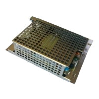
16 PRO-2200 Output Module PRO22OUTInstallation Guide
Note: For N-485 Communication Connections, twist the blue pair together and use as the common;
use the orange pair as your data pair, observing polarity. Connect the external drain shield to
the appropriate earth ground on one end.
Wiring Diagram for Connectors 7 through 11
Tamper
Switch Common
Power Fail
Tamper Switch
(In Close Position
when Cabinet Door
Is Closed)
C - No Charging
N/C - No Charging
+12VDC Power
Supply
+
DC Output
-
Relay 15 NC
Relay 15 C
Relay 15 NO
PWR+
PWR-
16 OUTPUT
BOARD
1
2
3
4
5
6
1
2
3
RS-485 Power
J1 - RS485
Termination
Jumper
1
2
3
4
5
6
7
8
S1
1
2
3
4
5
6
1
2
3
D12
Configuration
Dip Switches
1
2
1
2
3
4
5
6
1
2
3
4
5
6
1
2
3
4
5
6
1
2
3
4
5
6
1
2
3
4
5
6
D16
D18
D11
D13
D15
D14
D17
D6
D8
D10
D4
D1
D2
D3
D7
D9
D5
1
2
3
4
5
6
Relay 16 NC
Relay 16 C
Relay 16 NO
Relay 13 NC
Relay 13 C
Relay 13 NO
Relay 14 NC
Relay 14 C
Relay 14 NO
PWR+
PWR-
NC
Chassis
GND
At Other
Panel
RS 485
Com Bus Cable
From Diff.
Panel
(Remote
Mount Only)
485-Com +
485-Com -
Com-Gnd
The connectors on this
side of the board are not
Accessible when it is
rack mounted.
Connect to
chassis GND at
One side ONLY

 Loading...