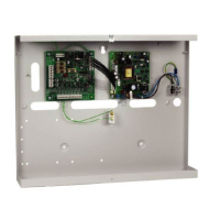
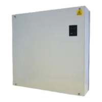
PRO-2200 Output Module PRO22OUT 9Installation Guide
N-1000-IV FourN-1000-IV Four
N-1000-IV FourN-1000-IV Four
N-1000-IV Four
Reader BoardReader Board
Reader BoardReader Board
Reader Board
Description
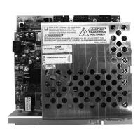
The Output Board provides connections for 16 relay outputs. This board can be rack
mounted, in which case, only one edge is accessible for wiring. Mounting the board flat
increases the amount of available I/O slightly but also significantly decreases the number
of boards that can be mounted in one enclosure.
Starting at the bottom of the rack-mount side of the board, the first connector provides
power to the board. The next connector provides communication with the Controller
(PRO22IC). Continuing up this edge, the next 6 connectors provide 12 relay output
connections.
When the board is mounted flat, four additional relay outputs and two dedicated alarm
inputs for cabinet tamper and power fault detection are available on the opposite edge of
the board.
All 16 form-C relay outputs are designed to handle dry-circuit signals. The two dedicated
inputs are non-supervised. Communication to the control panel is accomplished via an
RS-485 interface. This board requires 12 VDC input power.
When communication to the Controller is lost, this board maintains all previous output
settings at the time communication was lost.
Set Up
Jumper Settings:
repmuJ gnitteS tluafeD detceleS
1J
FFO
*
evitcatonsirotanimretLOE584-SR1troP
NOevitcasirotanimretLOE584-SR1troP

 Loading...
